NX-SL/SI/SO
10
External Interface
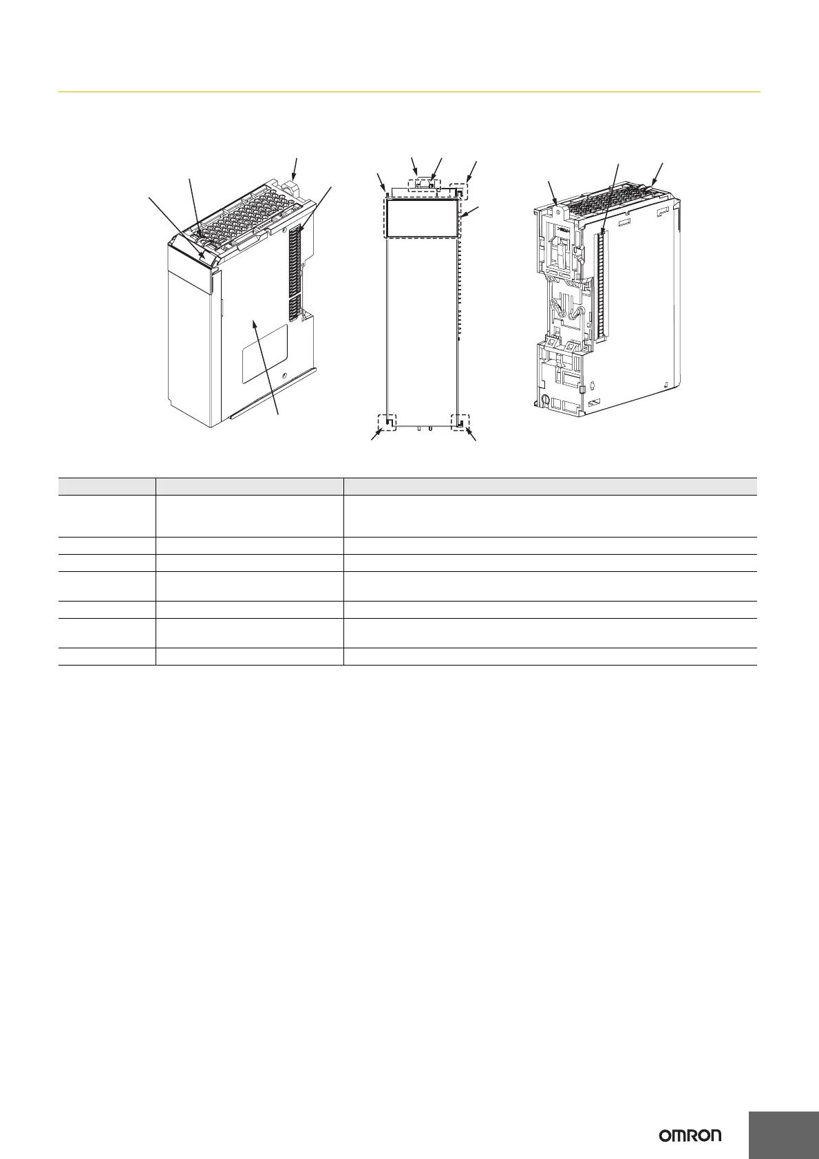
Safety CPU Unit
NX-SL3300/SL3500
Letter Item Specification
A Marker attachment locations
The locations where markers are attached. The markers made by OMRON are
installed for the factory setting. Commercially available markers can also be
installed. For details, refer to User's Manual (Z930-E1).
B Protrusions for removing the Unit The protrusions to hold when removing the Unit.
C DIN Track mounting hooks These hooks are used to mount the NX Unit to a DIN Track.
D NX bus connector
This is the NX-series bus connector. It is used to connect an NX-series Safety I/O
Unit or other NX Unit.
E Unit hookup guides These guides are used to connect two Units.
F Indicators
The indicators show the current operating status of the NX Unit or signal I/O status.
Refer to User's Manual (Z930-E1).
G Unit specifications The specifications of the NX Unit are given here.
(D)
(D)
(E)
(C)
(G)
(F)
(E)
(A)
(C)
(C)
(B)
(E)
(B)
(B)
(E)

 Loading...


