11
NX-SL/SI/SO
Safety Input Unit NX-SIH400/SID800
Safety Output Unit NX-SOH200/SOD400
Terminal Blocks
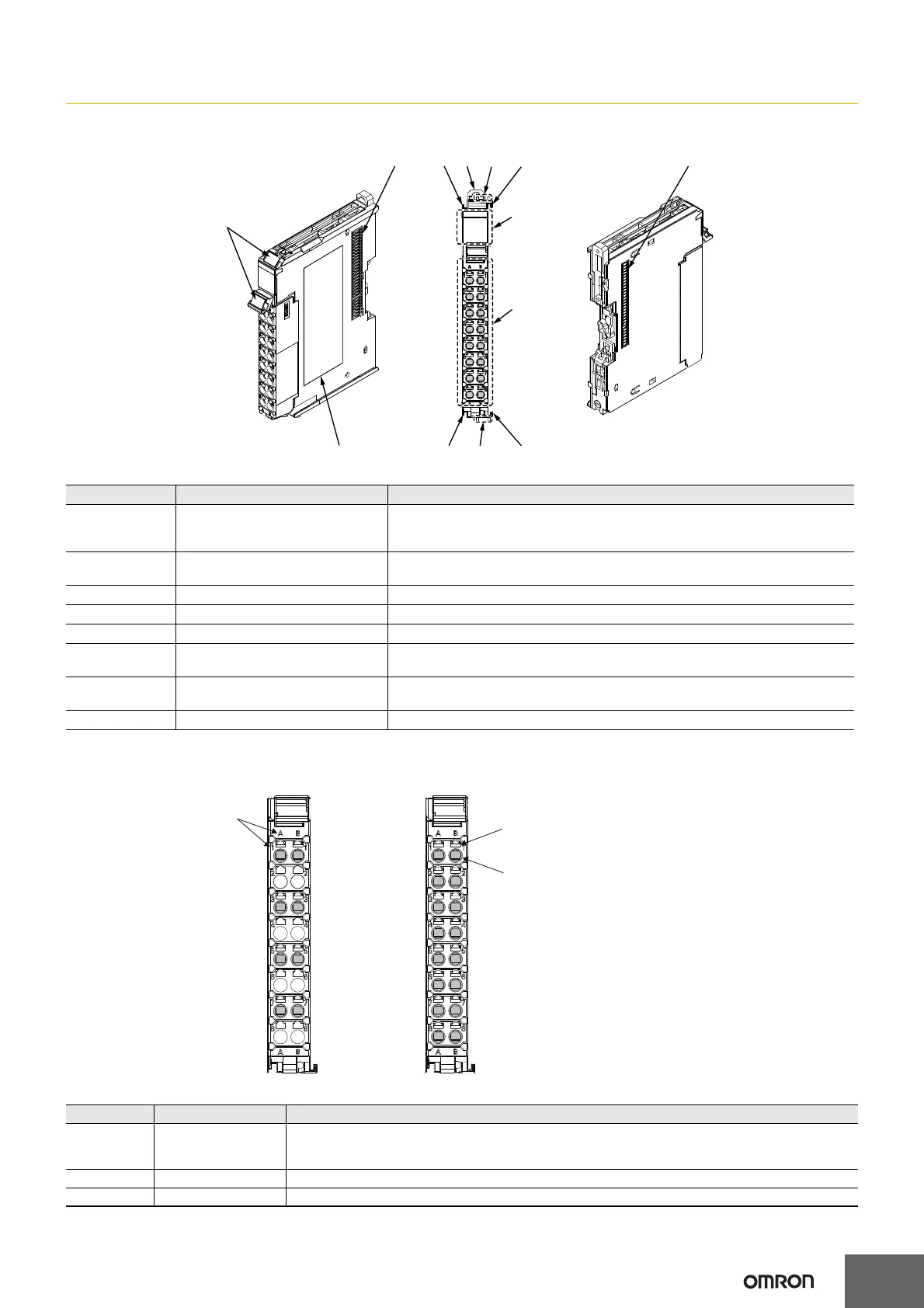
Letter Item Specification
A Marker attachment locations
The locations where markers are attached. The markers made by OMRON are
installed for the factory setting. Commercially available markers can also be
installed. For details, refer to User's Manual (Z930-E1).
B NX bus connector
This is the NX-series bus connector. Connect this connector to another Unit, such as
the NX-series Safety CPU Unit or a Safety I/O Unit.
C Unit hookup guides These guides are used to connect two Units.
D DIN Track mounting hooks These hooks are used to mount the NX Unit to a DIN Track.
E Protrusions for removing the Unit The protrusions to hold when removing the Unit.
F Indicators
The indicators show the current operating status of the NX Unit or signal I/O status.
Refer to User's Manual (Z930-E1).
G Terminal block
The terminal block is used to connect to external devices. It connects the safety
outputs. The number of terminals depends on the NX Unit.
H Unit specifications The specifications of the NX Unit are given here.
Letter Item Specification
(A)
Terminal number
indications
The terminal numbers are given by column letters A and B, and row numbers 1 to 8. The combination of
the column and row gives the terminal numbers from A1 to A8 and B1 to B8. The terminal number
indicators are the same regardless of the number of terminals on the terminal block, as shown above.
(B) Release holes Insert a flat-blade screwdriver into these holes to connect and remove the wires.
(C) Terminal holes The wires are inserted into these holes.
(C)(D)
(H)
(G)
(F)
(C)
(A)
(E)
(C)(E)
(C)
(B)
(B)
8-terminal type
(B)
16-terminal type
(C)
(A)
A1
A2
A3
A4
A5
A6
A7
A8
B1
B2
B3
B4
B5
B6
B7
B8
A1
A2
A3
A4
A5
A6
A7
A8
B1
B2
B3
B4
B5
B6
B7
B8

 Loading...


