NX-SL/SI/SO
12
Applicable Terminal Blocks for Each Unit Model
Applicable Wires
Using Ferrules
If you use ferrules, attach the twisted wires to them.
Observe the application instructions for your ferrules for the wire stripping length when attaching ferrules.
Always use one-pin ferrules. Do not use two-pin ferrules.
The applicable ferrules, wires, and crimping tool are given in the following table.
* Some AWG 14 wires exceed 2.0 mm
2
and cannot be used in the screwless clamping terminal block.
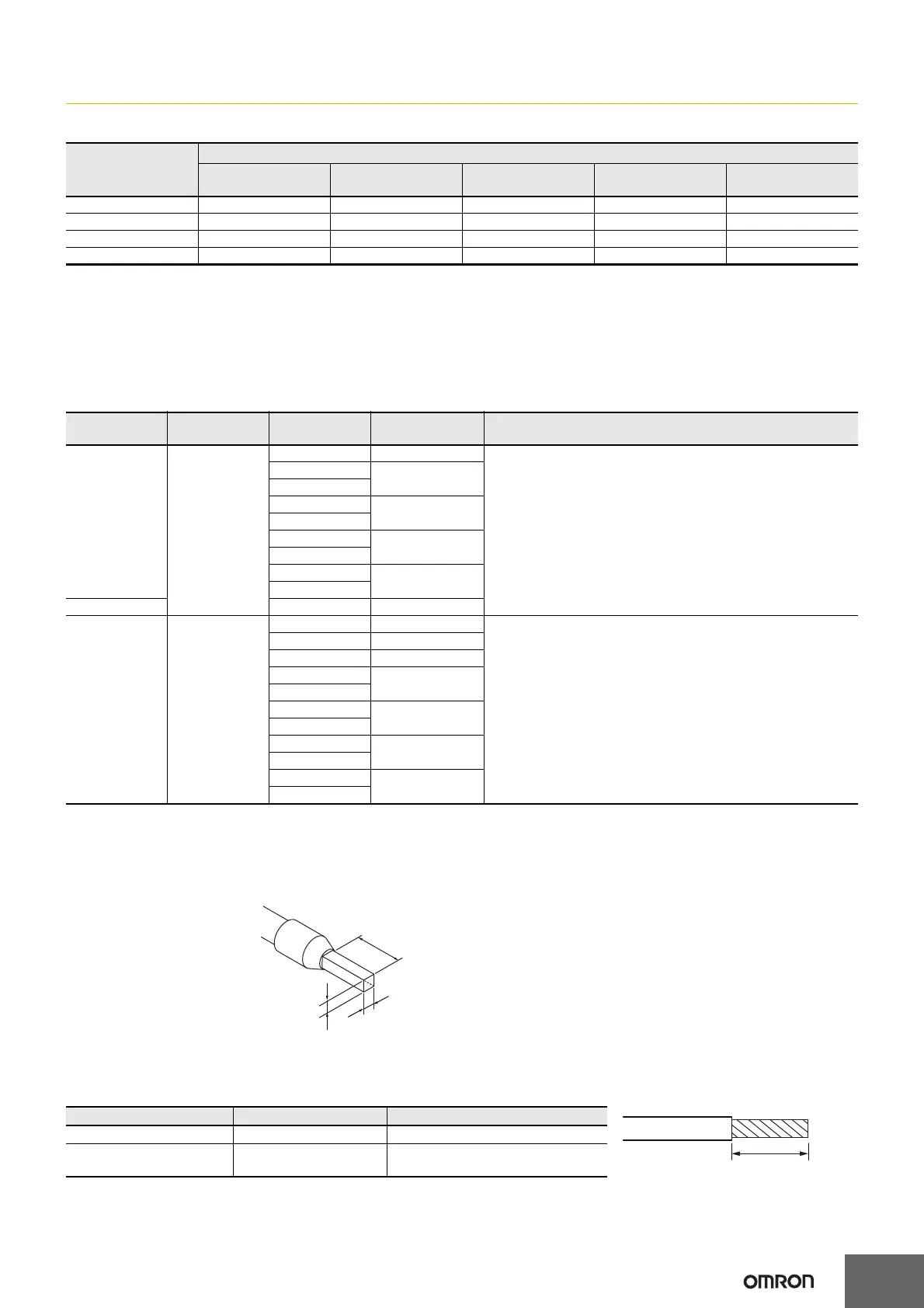
When you use any ferrules other than those in the above table, crimp them to the twisted wires so that the following processed dimensions are
achieved.
Using Twisted Wires/Solid Wires
If you use the twisted wires or the solid wires, the applicable wire range and conductor length (stripping length) are as follows.
Use the twisted wires to connect the ground wire to a ground of 100 Ω or less. Do not use the solid wires.
Unit model
number
Terminal Blocks
Model
No. of
terminals
Terminal number
indications
Ground terminal
mark
Terminal current
capacity
NX-SIH400 NX-TBA082 8 A/B None 10A
NX-SID800 NX-TBA162 16 A/B None 10A
NX-SOH200 NX-TBA082 8 A/B None 10A
NX-SOD400 NX-TBA082 8 A/B None 10A
Terminal types Manufacturer
Ferrule model
number
Applicable wire
(mm
2
(AWG))
Crimping tool
Terminals other
than ground
terminals
Phoenix Contact AI0,34-8 0.34 (#22) Phoenix Contact (The figure in parentheses is the applicable wire size.)
CRIMPFOX 6 (0.25 to 6 mm
2
, AWG24 to 10)
AI0,5-8 0.5 (#20)
AI0,5-10
AI0,75-8 0.75 (#18)
AI0,75-10
AI1,0-8 1.0 (#18)
AI1,0-10
AI1,5-8 1.5 (#16)
AI1,5-10
Ground terminals AI2,5-10 2.0 *
Terminals other
than ground
terminals
Weidmuller H0.14/12 0.14 (#26) Weidmuller (The figure in parentheses is the applicable wire size.)
PZ6 Roto (0.14 to 6 mm
2
, AWG 26 to 10)
H0.25/12 0.25 (#24)
H0.34/12 0.34 (#22)
H0.5/14 0.5 (#20)
H0.5/16
H0.75/14 0.75 (#18)
H0.75/16
H1.0/14 1.0 (#18)
H1.0/16
H1.5/14 1.5 (#16)
H1.5/16
Terminal types Applicable wires Conductor length (stripping length)
Ground terminals 2.0 mm
2
9 to 10 mm
Terminals other than ground
terminals
0.08 to 1.5 mm
2
AWG28 to 16
8 to 10 mm
Finished Dimensions of Ferrules
1.6 mm max. (except ground terminals)
2.0 mm max. (ground terminals)
2.4 mm max. (except ground terminals)
2.7 mm max. (ground terminals)
8 to 10 mm
Conductor length (stripping length)

 Loading...


