7.IO-Link Connection Procedure
13
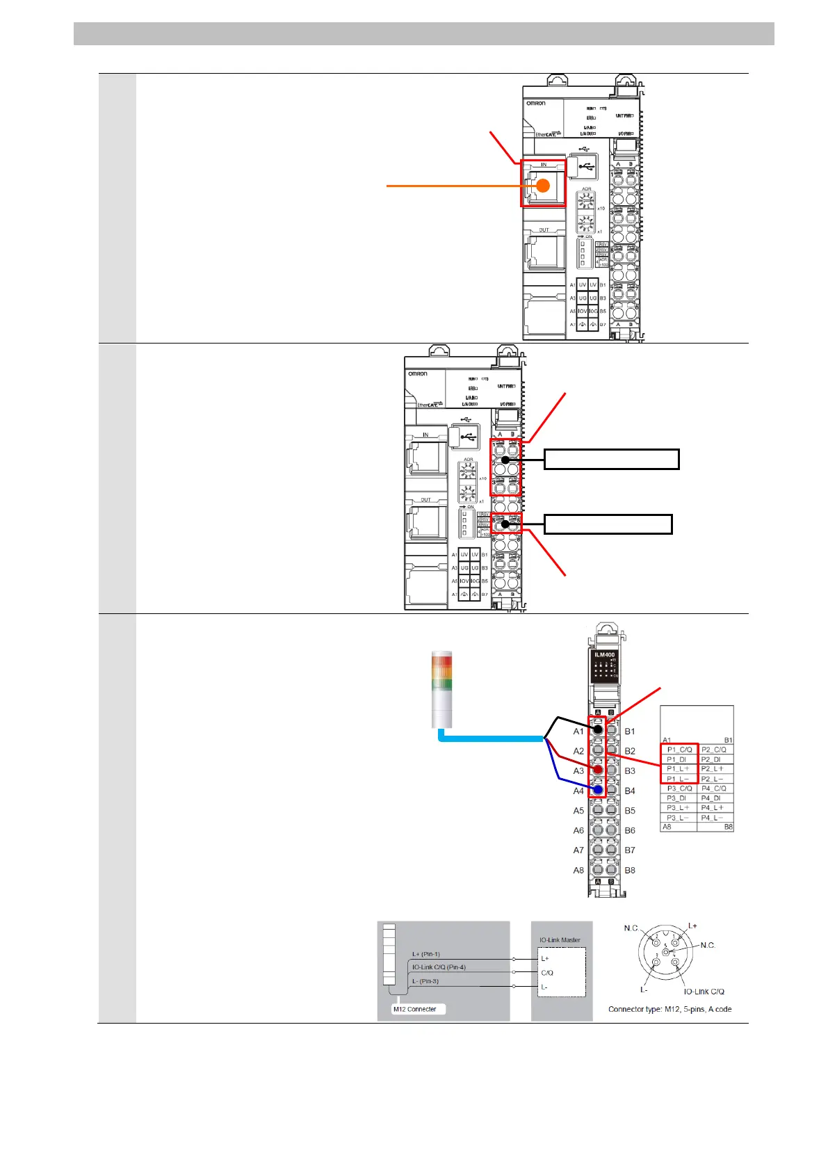
5
Connect an Ethernet cable to
Communications connector (IN)
on EtherCAT Coupler Unit.
Connect Unit power supply and
I/O power supply to Unit power
supply terminals and I/O power
supply terminals on EtherCAT
Coupler Unit, respectively.
*Refer to the NX-series
EtherCAT® Coupler Unit User's
Manual (Cat. No. W519) for
information on wiring the power
supplies to NX-series Slave
Terminal.
Connect Signal Tower and Port
1 on IO-Link Master Unit with a
Communication cable.
*For information on the
connector specifications of
Signal Tower, refer to the
IO-Link Signal Tower TYPE
LR6-IL Complete Operation
Manual (GA0001002).
connector (IN)
Unit power supply terminals
I/O power supply terminals

 Loading...


