Machine Automation Controller NX1
30
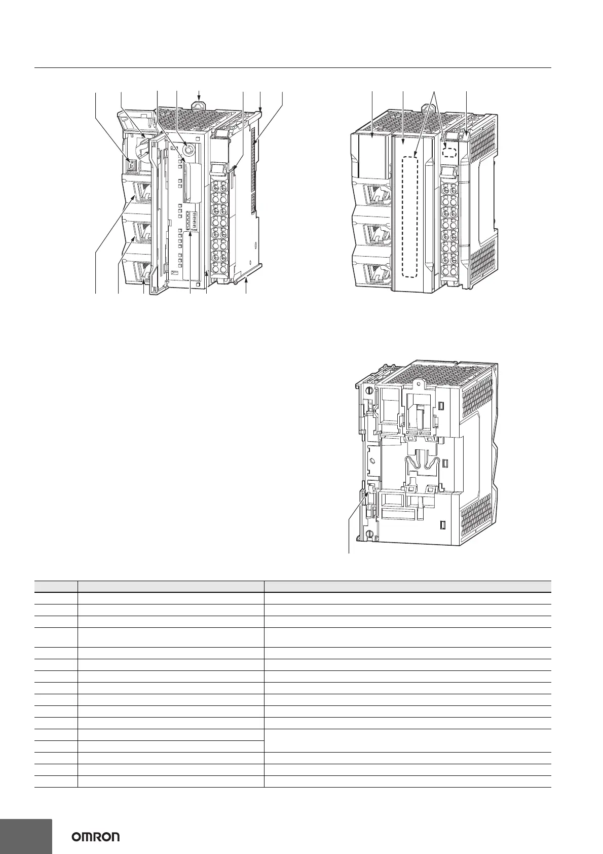
Part Names and Functions
Letter Name Function
A Battery connector Connects a separately-sold backup battery to the CPU Unit.
B Battery slot Allows a separately-sold backup battery to be mounted into the CPU Unit.
C SD Memory Card connector Connects the SD Memory Card to the CPU Unit.
D SD Memory Card power supply switch
Turns OFF the power supply so that you can remove the SD Memory Card.
NX-series NX102 CPU Unit Hardware User’s Manual (W593)
E DIN Track mounting hook This hook is used to mount the NX Unit to a DIN Track.
F Terminal block The terminal block is used for wiring for the Unit power supply and grounding cable.
G Unit hookup guides These guides are used to mount an NX Unit or the End Cover.
H NX bus connector This connector is used to connect the NX Unit mounted on the right side.
I ID information indication Shows the ID information of the CPU Unit.
J DIP switch Used in Safe Mode*
1
or when backing up data*
2
. Normally, turn OFF all of the pins.
K Built-in EtherCAT port (port 3) Connects the built-in EtherCAT with an Ethernet cable.
L Built-in EtherNet/IP port (port 2)
Connects the built-in EtherNet/IP with an Ethernet cable.
Use port 1 to perform OPC UA communications.
M Built-in EtherNet/IP port (port 1)
N Battery cover A cover for the battery slot. It opens upward.
O SD Memory Card A cover for the SD Memory Card and the DIP switch. It opens toward the left.
P Operation Status Indicators Shows the operation status of the CPU Unit by multiple indicators.
(A)
(B)
(C) (D)
(G) (H)
(E)
(F)
(N)
(I)
(O) (Q)(P)
(J)(M) (K)(L) (G)
(R)

 Loading...


