7 Applied Functions
7 - 6
G5-series Linear Motors/Servo Drives With Built-in EtherCAT Communications
Input the setting for each control mode to any of the objects from 3410 to 3411 hex to allocate the
signals.
Set the objects based on hexadecimal in the same manner as for the input signal allocations.
Set the set value of the function for each control mode in “ ** ” below.
For the set value of each function, refer to Function Number Table on page 7-6.
The logic setting is included in the function numbers.
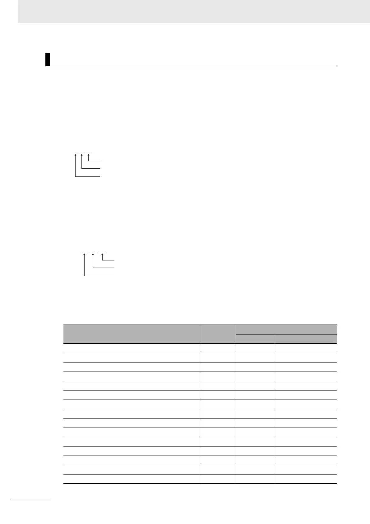
Example:
z Function Number Table
The set values to be used for allocations are as follows:
Output Signal Allocation Method
Position Control : Position command output (08 hex)
Speed control : Motor speed detection output (05 hex)
Force control : Zero speed detection signal (07 hex)
Signal name Symbol
Set value
NO NC
Disabled – 00 hex 00 hex
Servo Ready Output READY 02 hex 82 hex
Brake Interlock Output BKIR 03 hex Setting not available
Positioning Completion Output INP1 04 hex 84 hex
Motor Speed Detection Output TGON 05 hex 85 hex
Force Limiting Signal TLIMT 06 hex 86 hex
Zero Speed Detection Output ZSP 07 hex 87 hex
Speed Conformity Output VCMP 08 hex 88 hex
Warning Output 1 WARN1 09 hex 89 hex
Warning Output 2 WARN2 0A hex 8A hex
Position Command Status Output PCMD 0B hex 8B hex
Positioning Completion Output 2 INP2 0C hex 8C hex
Speed limiting output VLIMT 0D hex 8D hex
Error Clear Attribute Output ALM-ATB 0E hex 8E hex
Speed Command Status Output VCMD 0F hex 8F hex
00
******
hex
Position control
Speed control
Force control
00070508 hex
Position control
Speed control
Force control
 Loading...
