4-18
4-2 Wiring
OMNUC G5-series AC Servomotors and Servo Drives User’s Manual (with Built-in EtherCAT Communications)
4
System Design
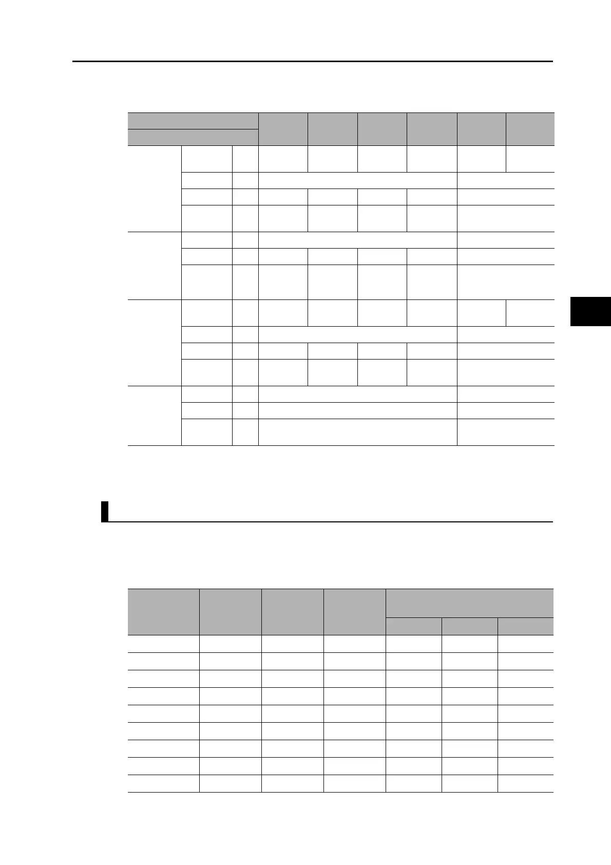
400 VAC Input Drive Wire Sizes: R88D-KN@@F-ECT-R
*1. Use the same wire sizes for B1 and B2.
*2. Connect an OMRON power cable to the motor connection terminals.
Wire Sizes and Allowable Current (Reference)
The following table shows the allowable current when there are 3 power supply wires. Use a
current below these specified values.
600-V Heat-resistant Vinyl Wire (HIV)
Model (R88D-)
KN06F-
ECT-R
KN10F-
ECT-R
KN15F-
ECT-R
KN20F-
ECT-R
KN30F-
ECT-R
KN50F-
ECT-R
Item Unit
Main circuit
power
supply input
(L1 and L3,
or L1, L2
and L3)
Rated
current
A 2.1 2.8 3.9 5.9 7.6 12.1
Wire size − AWG14 AWG12
Screw size −− − − − M5
Tightening
torque
N·m −−−− 2.0
Control
circuit
power
supply input
(L1C and
L2C)
Wire size − AWG20 to 24 AWG18
Screw size −− − − − M5
Tightening
torque
N·m −−−− 2.0
Motor
connection
terminals
(U, V, W,
and FG)
*1 *2
Rated
current
A 1.5 2.9 4.7 6.7 9.4 16.5
Wire size − AWG14 AWG12
Screw size −− − − − M5
Tightening
torque
N·m −−−− 2.0
Frame
ground (FG)
Wire size − AWG14 AWG12
Screw size − M4 M5
Tightening
torque
N·m 1.2 2.0
AWG size
Nominal cross-
sectional area
(mm
2
)
Configura-
tion (wires/
mm
2
)
Conductive
resistance
(Ω/km)
Allowable current (A) for ambient
temperature
30°C 40°C 50°C
20 0.5 19/0.18 39.5 6.6 5.6 4.5
− 0.75 30/0.18 26.0 8.8 7.0 5.5
18 0.9 37/0.18 24.4 9.0 7.7 6.0
16 1.25 50/0.18 15.6 12.0 11.0 8.5
14 2.0 7/0.6 9.53 23 20 16
12 3.5 7/0.8 5.41 33 29 24
10 5.5 7/1.0 3.47 43 38 31
8 8.0 7/1.2 2.41 55 49 40
6 14.0 7/1.6 1.35 79 70 57
 Loading...
