8-38
8-5 Interface Monitor Setting Parameters
OMNUC G5-SERIES AC SERVOMOTOR AND SERVO DRIVE USER'S MANUAL
8
Parameter Details
Explanation of Set Values
*1. Forward and reverse directions of monitor data are the direction set in Pn000. However, CCW will be
the forward direction for the absolute encoder 1-rotation data. A normal value is output from the
incremental encoder after the first phase Z is input.
*2. Analog inputs 1 to 3 will output terminal voltage even when terminal is not used.
*3. Corresponding to command pulse input, command pulse speed is before command filter (position
command filter time constant and smoothing filter time constant), and internal command speed is after
command filter.
*4. The position command error is an error from the command pulse input, while the encoder position
error or fully-closed position error is the error at the input of the position loop.
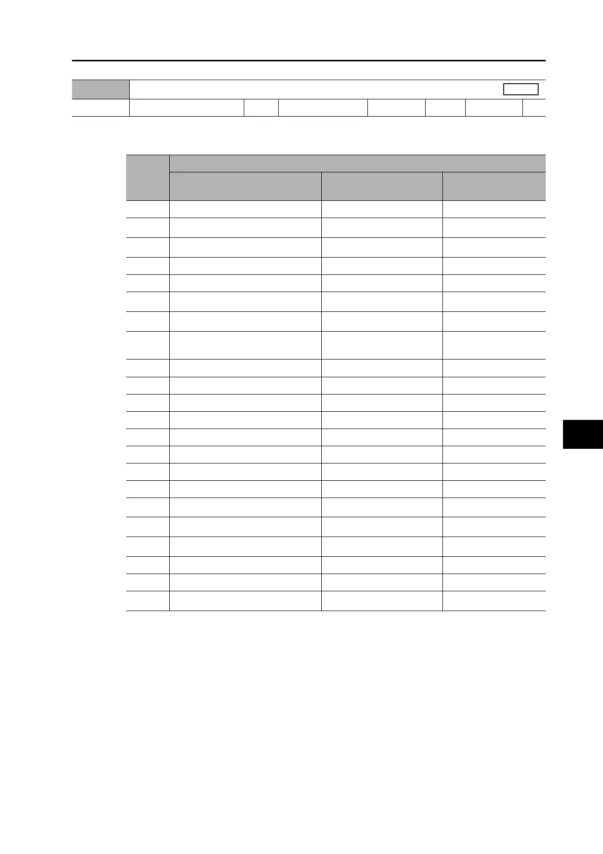
Pn416
Analog Monitor 1 Selection
Setting range
0 to 21 Unit −
Default setting
0
Power OFF and ON
−
Set
value
Explanation
Monitor type Unit
Output gain when
Pn417 = 0
0 Motor speed r/min 500
1
Position command speed *
3
r/min
500
2
Internal position command speed *
3
r/min
500
3 Speed control command r/min 500
4 Torque command % (rated torque ratio) 33
5
Position command error *
4
pulse (command units)
3,000
6
Encoder position error *
4
pulse (encoder units)
3,000
7
Fully-closed error *
4
pulse (external encoder
units)
3,000
8 Hybrid Error pulse (command units) 3,000
9 P-N voltage V 80
10 Regeneration load ratio % 33
11 Overload load ratio % 33
12 Forward direction torque limit % (rated torque ratio) 33
13 Reverse direction torque limit % (rated torque ratio) 33
14 Speed limit value r/min 500
15 Inertia ratio % 500
16
Analog input 1 *
2
V
1
17
Analog input 2 *
2
V
1
18
Analog input 3 *
2
V
1
19 Encoder temperature °C 10
20 Drive temperature °C 10
21
Encoder 1-rotation data *
1
pulse (encoder units)
110,000

 Loading...


