3-47
3-1 Servo Drive Specifications
OMNUC G5-SERIES AC SERVOMOTOR AND SERVO DRIVE USER'S MANUAL
3
Specifications
Encoder Outputs (Phases A, B and Z)
Pin 21: +A, 22: -A, 48: -B, 49: +B, 23: +Z, 24: -Z
Function
It outputs the phase A, phase B, and phase Z encoder signals for the Servomotor.
The encoder outputs conform to the RS-422 communication method.
You can use External Feedback Pulse Dividing Numerator Setting (Pn324) and External
Feedback Pulse Dividing Denominator Setting (Pn325) to set the dividing ratio.
The logical relation of phase B to the phase A pulse and whether to set the output source to an
encoder or external encoder can be selected with Encoder Output Direction Switching Selection
(Pn012).
The ground for the output circuit line driver is connected to the signal ground (ZGND). It is not
isolated.
The maximum output frequency is 4 Mpps (after quadruple multiplier).
The output frequency = the motor encoder resolution × (Pn324/Pn325) × 4 × motor rotation speed
(r/min)/60
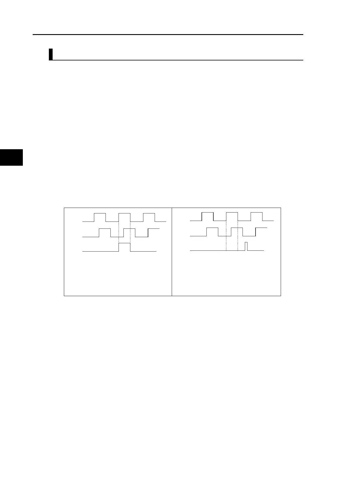
The output phases are as shown below. (They are the same for both incremental and absolute
encoders.)
If the motor encoder
resolution × Pn324/Pn325
is a multiple of 4, phases Z
and A are synchronized.
In cases except for the one
on the left, phases A and Z
are not synchronized.
Phase A
Phase B
Phase Z
Synchronous
Phase A
Phase B
Phase Z
Asynchronous
 Loading...
