Switch Mode Power Supply S8JX 3
Connections
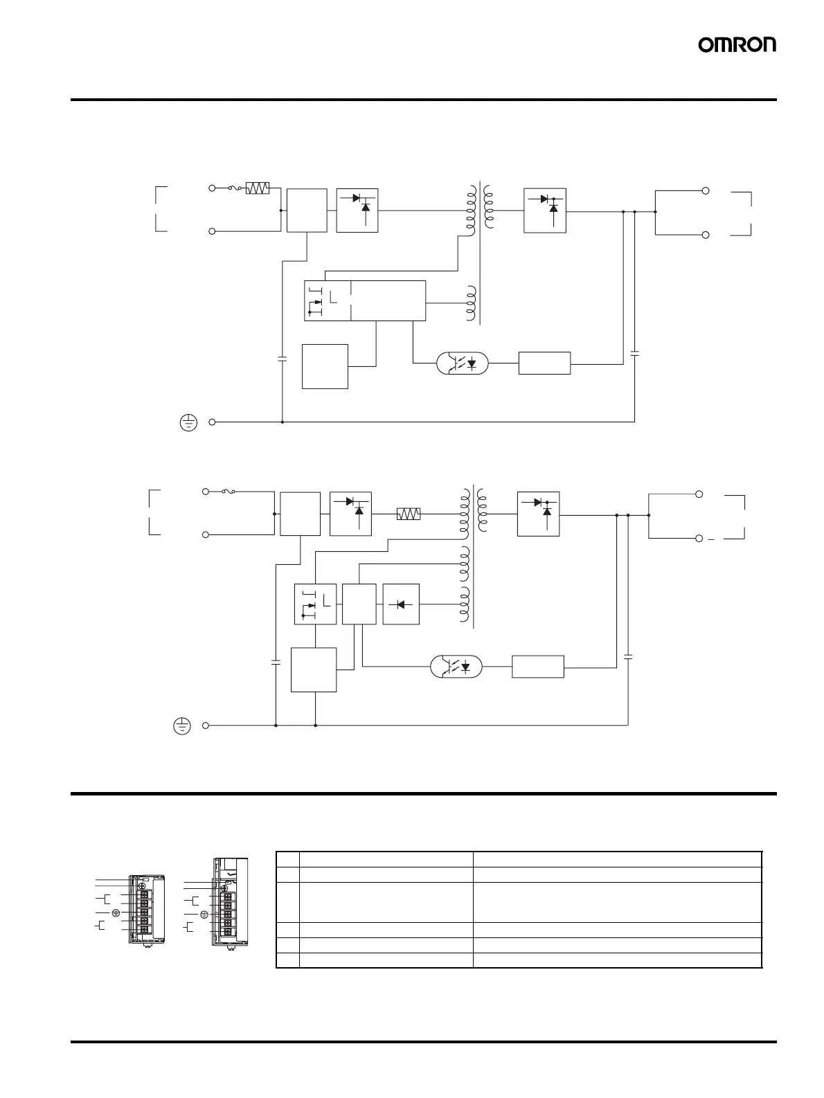
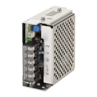
■ Block Diagrams
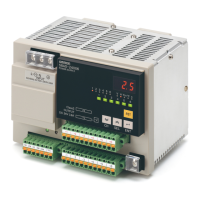
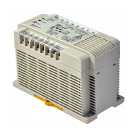
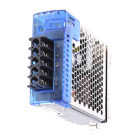
Construction and Nomenclature
■ Nomenclature
+V
−V
Input
AC (L)
AC (N)
Fuse
3.15 A
Inrush
current
protection
Noise
filter
Rectifier
IPD IC
Control circuit
OCP
adjustment
circuit
Rectifier
Voltage
detection
DC Output
S8JX-035@@@@ (35 W)
S8JX-050@@@@ (50 W)
In
u
AC
L
AC
N
F
Inrush
current
protection
Noise
filter
Rectifier
Control
circuit
OCP
adjustment
circuit
Rectifier
Voltage
detection
DC Out
u
Input
compensation
S8JX-100@@@@ (100 W)
S8JX-150@@@@ (150 W)
Note: 1. This is the protective earth terminal specified in the safety standards.
Always ground this terminal.
2. The fuse is located on the (L) side. It is NOT user-replaceable.
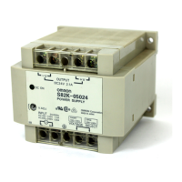
No. Name Function
1 Output indicator (DC ON: Green) Lights while a direct current (DC) output is ON.
2 Output voltage adjuster (V. ADJ) Use to adjust the voltage.
It is possible to increase or decrease the output voltage
by
−10% to 15%
3 DC output terminals (
−V). (+V) Connect the load lines to these terminals.
4 Protective Earth terminal (PE) Connect the ground line to these terminals. (See note 1.)
5 AC input terminals (L). (N) Connect the input lines to these terminals. (See note 2.)
35/50 W 100/150 W
+V
−V
AC(L)
AC(N)
+V
−V
AC(L)
AC(N)
1
2
3
4
5
1
2
3
4
5