4 Switch Mode Power Supply S8JX
Engineering Data
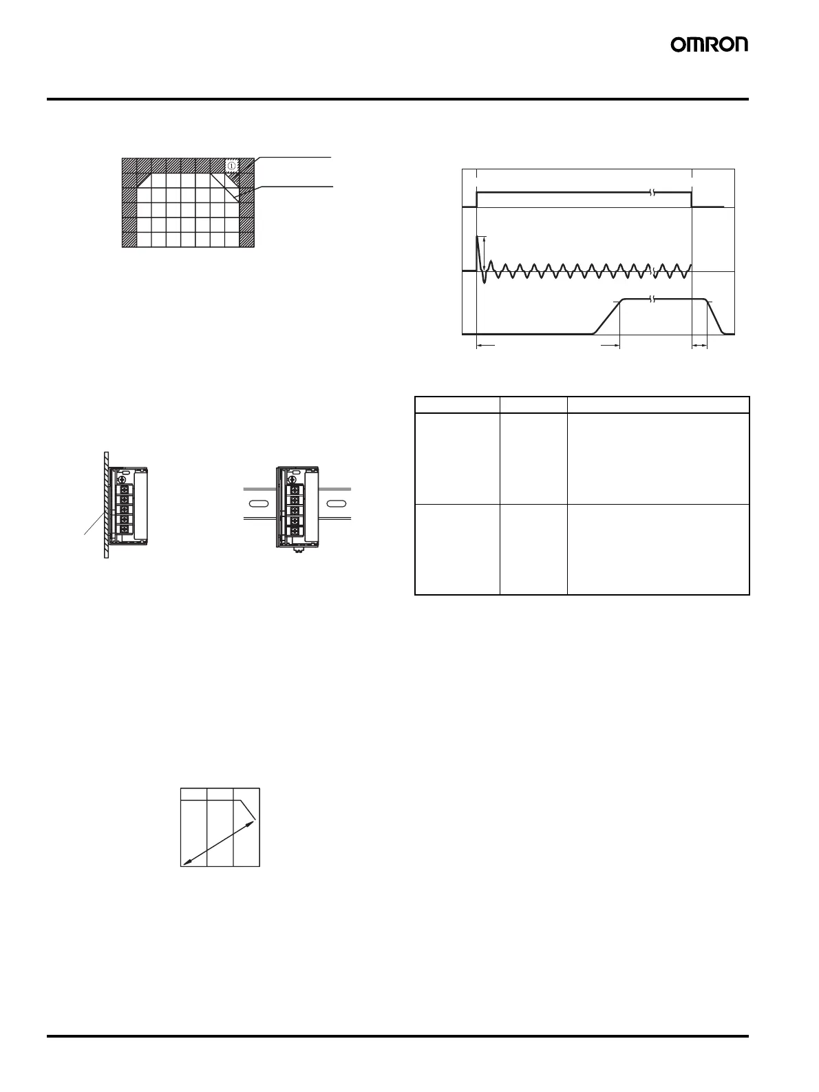
■ Derating Curve
Note: 1. Internal parts may occasionally deteriorate or be damaged.
Do not use the Power Supply in areas outside the derating
curve (i.e., the area shown by shading A in the above
graph).
2. If there is a derating problem, use forced air-cooling.
3. The peripheral temperature is specified at the place 75 mm
downward from the main body of Power Supply unit.
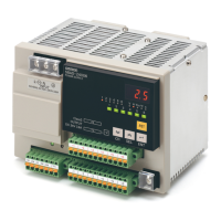
■ Mounting
Note: 1. Improper mounting will interfere with heat dissipation and
may occasionally result in deterioration or damage of
internal parts. Use the standard mounting method only.
2. When mounting the Power Supply, mounting it to a metal
plate (*1) is recommended.
3. Install the Power Supply so that the air flow circulates
around the Power Supply, as the Power Supply is designed
to radiate heat by means of natural air flow.
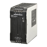
■ Overload Protection
The Power Supply is provided with an overload protection function
that protects the power supply from possible damage by overcurrent.
When the output current rises above 105% min. of the rated current,
the protection function is triggered, decreasing the output voltage.
When the output current falls within the rated range, the overload
protection function is automatically cleared.
The values shown in the above diagram are for reference only.
Note: 1. Internal parts may occasionally deteriorate or be damaged
if a short-circuited or overcurrent state continues during op-
eration. Remove the cause of the short-circuited or overcur-
rent state as quickly as possible.
2. Internal parts may possibly deteriorate or be damaged if the
Power Supply is used for applications with frequent inrush
current or overloading at the load end. Do not use the Power
Supply for such applications.
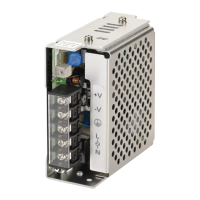
■ Inrush Current, Start Up Time,
Output Hold Time
■ Reference Values
Ambient Temperature (°C)
Load rate (%)
120
100
80
60
40
20
0
−20 −10
20010 3040506070
without cover,
standard mounting
with cover,
standard mounting
Standard Mounting
(Front-mounting type)
Standard Mounting
(DIN Rail mounting bracket type)
∗1
0 50% 100%
Load rate (%)
Output voltage (V)
Item Value Definition
Reliability 500,000 hrs.
min.
MTBF stands for Mean Time Be-
tween Failures, which is calculated
according to the probability of acci-
dental device failures, and indicates
reliability of devices.
Therefore, it does not necessarily
represent a life of the Product.
Life expectancy 5 yrs. min. The life expectancy indicates aver-
age operating hours under the ambi-
ent temperature of 40
°C and a load
rate of 50%.
Normally this is determined by the
life expectancy of the built-in alumi-
num electrolytic capacitor.
90%
96.5%
Start up time (1,500 ms max.)
AC input
voltage
AC input
current
Output
voltage
Inrush current on input application
Input OFF
Input ON
Hold time
(20 ms min.)