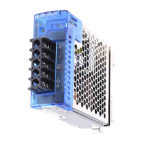
S8VS
480-W Models
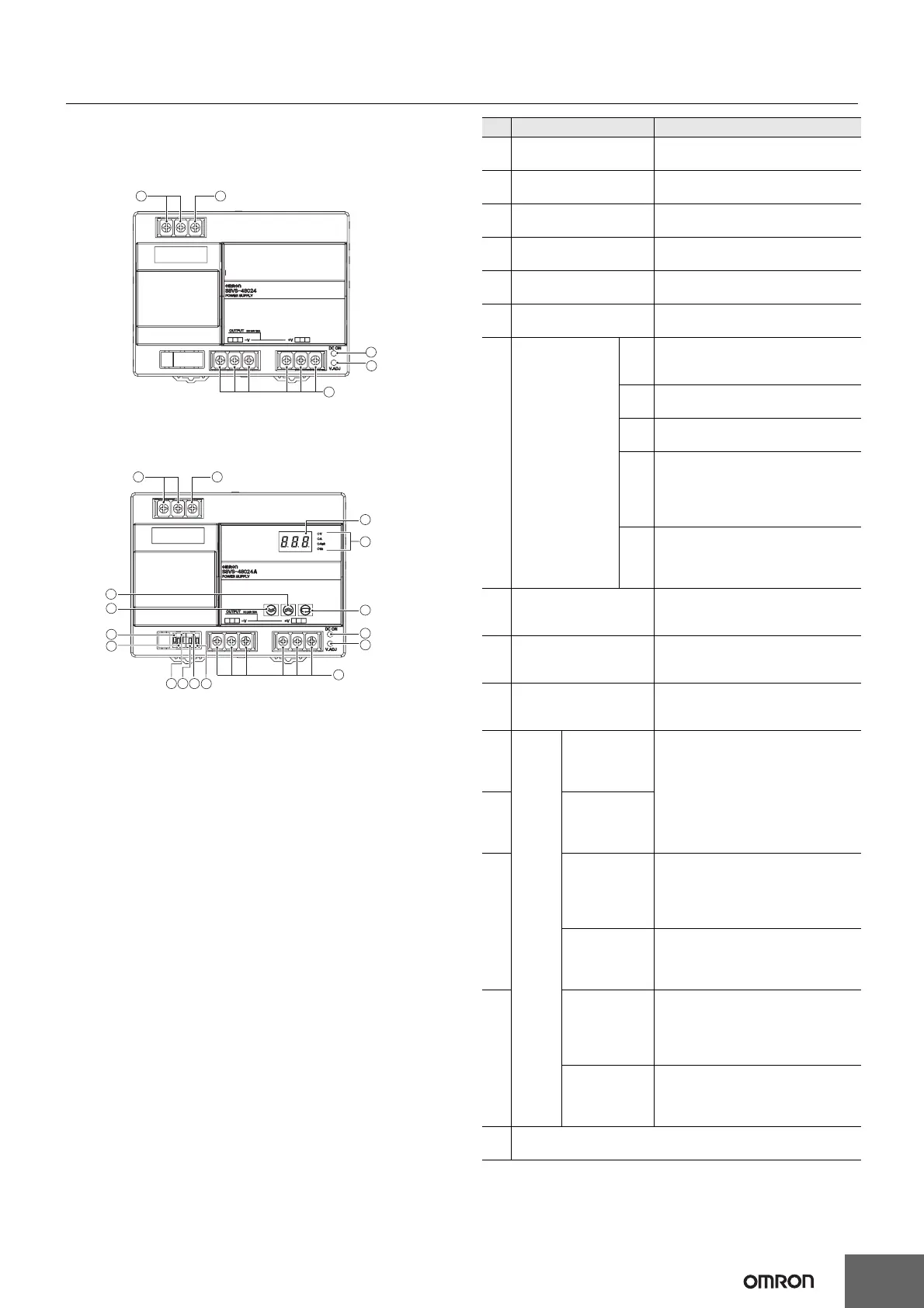
No. Name Function
Standard Model
1
AC Input terminals Connect the input lines to these
(L), (N) terminals. *1
S8VS-48024
Protective Earth Connect the ground line to this
1 2
2
terminal (PE) terminal. *2
DC Output terminals Connect the load lines to these
3
(−V), (+V) terminals.
Output indicator Lights while a direct current (DC)
4
(DC ON: Green) output is ON.
5
Output voltage adjuster
Use to adjust the voltage.
(V.ADJ)
6 Main display (Red) *3
Indicates the measurement or set
value.
Lights up when the output voltage is
4
V indicated. Blinks during setup of
5
undervoltage alarm value.
3
Lights up during indication of output
A
current.
Models with Indication Monitor
Lights up during indication of peak
S8VS-48024@
Operation
Apk
hold current.
7 indicator
Lights up during indication of
1 2
(Orange) *3
maintenance forecast monitor.
Yrs Blinks during setup of maintenance
forecast monitor setting. (S8VS-
6
48024A)
Lights up during indication of total
7
run time monitor. Blinks during setup
kh
of total run time monitor. (S8VS-
48024B)
9
Use the Mode Key to change the
10
8
8 Mode Key *3 indicated parameter or reset the
peak hold current value.
16
4
15
5
Use the Up Key to change to the
9Up Key *3 setting mode or to increase the set
3
value.
14 13
12
11
Note: The illustration shows the S8VS-48024A model.
Use the Down Key to change to the
10 Down Key *3 setting mode or to decrease the set
value.
* The terminal arrangement is the same for models with screwless
terminal blocks and standard models.
Undervoltage
output terminal
11
(DC Low)
(Emitter side)
Output when a drop is detected in
the output voltage (voltage drop =
Undervoltage
transistor OFF).
output terminal
12
(DC Low)
(Collector side)
Maintenance
Forecast Output when the set value for
output terminal maintenance is reached (transistor
(Yrs) *4 OFF).
13
Alarm
(Emitter side)
outputs
*3
Total run time
output terminal Output when the set value for total
(kh) *5 run time is reached (transistor OFF).
(Emitter side)
Maintenance
Forecast
Output when the set value for
output terminal
maintenance is reached (transistor
(
Yrs
) *4 OFF).
14
(Collector side)
Total run time
output terminal Output when the set value for total
(kh) *5 run time is reached (transistor OFF).
(Collector side)
15,
NC (Not connected)
16
*1. The fuse is located on the (L) side. It is NOT user replaceable.
*2. This is the protective earth terminal specified in the safety standards.
Always ground this terminal.
*3. S8VS-48024A/B only.
*4. S8VS-48024A only.
*5. S8VS-48024B only.
17