94
Overview of Analog I/O Units Section 5-1
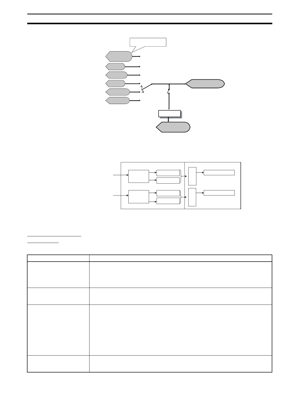
Flow of Data in Analog
Input Units
Note By default, analog input values are allocated as I/O just as they are.
For Inputs 0 and 1, analog data can be separately selected, as shown in the
following diagram.
5-1-6 I/O Data
GRT1-AD2 Analog
Input Units
Analog Input Units support the following four types of input data, and one type
of output data. The required data can be allocated for use as I/O.
Input Data
Moving average, scal-
ing enabled/disabled
Six types of data
Select one of the six types of data and
allocate as analog data.
Analog input
value 1
Peak value 2
Bottom value 3
Top val ue 4
Valley value 5
Rate of change 6
Analog Data
(allocated I/O data)
Allocated to I/O.
Default allocation:
Analog input value
Comparator
The Comparator can be used
with values allocated as analog
data.
Analog Status Flags
(allocated I/O data)
Input 0
Math
processing
Analog input
value
Other process-
ing results
Selected
processing
Analog Data
Input 1
Math
processing
Analog input
value
Other process-
ing results
Selected
processing
Analog Data
I/O data Details
Analog Data
(4 input bytes)
• Used to monitor analog data.
• Select one type of data from analog input value, peak value, bottom value, top value,
valley value, or rate of change. (Default allocation: Analog input value)
Note The comparator can be used with analog data.
Top/Valley Detection Timing
Flags (2 input bytes)
Top/Valley Detection Timing Flags are allocated in one word. These flags are allocated
together with the top value or valley value and are used to time reading the values held in
the Master.
Analog Status Flags (2 input
bytes)
Used to allocate the bits for the Comparator Result Flags, Top/Valley Detection Timing
Flags, and Off-wire Detection Flag. The function of each bit is as follows:
• Comparator Result Flags
Allow control of the judgement results only, without allocating analog values
• Top/Valley Detection Timing Flags
Used to time reading the values held as the top and valley values when both the top and
value values are allocated at the same time.
• Off-wire Detection Flags
Disconnections can be detected even when the analog values are not allocated.
Analog Data + Top/Valley
Detection Timing Flags (6
input bytes)
Allocation of Analog Data (4 bytes) followed by Top/Valley Detection Timing Flags (2 input
bytes)

 Loading...


