158 AC servo systems
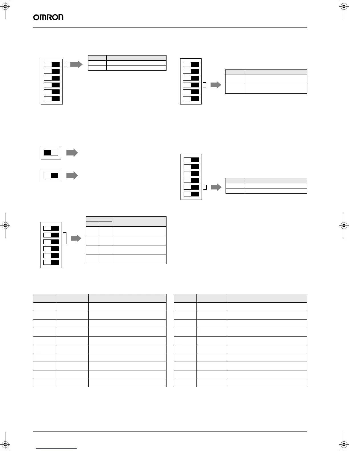
Enable switch/parameter setting
Pin 6 of the DIP switch selects whether the servo drive operates according to the
DIP switch settings or parameter settings
.
Online autotuning setting
The autotuning switch selects whether the gain will be adjusted auto-
matically during operation.
Resolution setting
Pins 4 and 5 select the positioning resolution.
If the resolution is set to 1,000 (the default setting), the motor makes
one revolution for every 1,000 pulses input.
Command pulse input setting
Pin 3 selects the command pulse mode. Select “Forward pulse/reverse
pulse: positive logic” or “feed pulses/direction signal: positive logic.”
Dynamic brake setting
Pin 2 enables or disables dynamic brake operation. If the dynamic brake is ena-
bled, the motor can be brought to an emergency stop when the RUN command
goes OFF or an alarm occurs.
Alarm Table
Note: 1. These parameters are read when the power is turned
ON. Parameter Pn110.2 is valid when online.
2. When using a regeneration resistor, set the resistor’s
capacity when the temperature has risen to 120 °C.
Set this parameter to 0 if a regeneration resistor is not
being used.
Pin 6 Function
OFF Enables the DIP switch settings.
ON Enables the parameter settings.
Pins Resolution
5 4
OFF OFF 1,000 pulses/revolution
(0.36°/step)
OFF ON 10,000 pulses/revolution
(0.036°/step)
ON OFF 500 pulses/revolution
(0.72°/step)
ON ON 5,000 pulses/revolution
(0.072°/step)
(Default setting)
6
5
4
3
2
1
ON OFF
1
1
ON OFF
ON OFF
Perform online autotuning.
Complete online autotuning.
The result is stored in the inertia ratio
parameter (Pn103) and the servo drive
runs.
6
5
4
3
2
1
ON OFF
(Default setting)
Pin 3 Command pulse mode
OFF Forward pulse/reverse pulse:
positive logic
ON Feed pulses/direction signal:
positive logic
Pin 2 Dynamic brake mode
OFF Dynamic brake disabled.
ON Dynamic brake enabled.
6
5
4
3
2
1
ON OFF
(Default setting)
6
5
4
3
2
1
ON OFF
(Default setting)
Display ALM output Error detection function Display ALM output Error detection function
A.04*
OFF
Parameter setting error A.7A
OFF
Overheat
A.10*
OFF
Overcurrent A.bF*
OFF
System error
A.30
OFF
Regeneration error A.C1
OFF
Runaway detected
A.32
OFF
Regeneration overload A.C2*
OFF
Phase not detected
A.40
OFF
Overvoltage/undervoltage A.C3*
OFF
Encoder disconnect detected
A.51
OFF
Overspeed A.d0
OFF
Deviation counter overflow
A.70
OFF
Overload CPF00
---
Parameter unit transmission error 1
A.73
OFF
Dynamic brake overload CPF01
---
Parameter unit transmission error 2
A.74
OFF
Inrush resistance overload A.91
---
Overload warning
A.92
---
Regeneration overload warning
Y203-EN2-02-Katalog.book Seite 158 Mittwoch, 24. Mai 2006 2:22 14
 Loading...