160 AC servo systems
Note: * A regeneration resistor can be connected across the B1 and B2 terminals with 400 W and 750 W servo drives.
When using an external regeneration resistor with a 400 W servo drive, just connect it across the B1 and B2 terminals.
When using an external regeneration resistor with a 750 W servo drive, remove the jumper bar from the B2 and B3 terminals and then
connect the regeneration resistor across the B1 and B2 terminals.
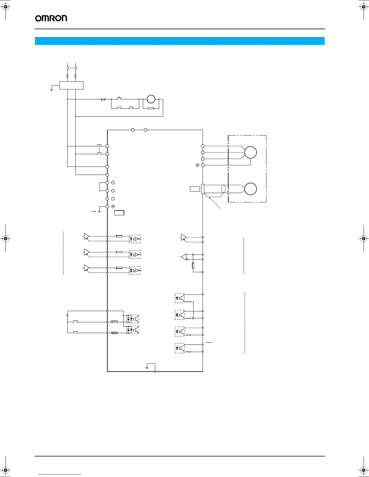
Installation
M
RE
U
V
W
ALMCOM
18
RESET
RUN
+24VIN
24 VDC
14
13
6
5
4
3
2
1
200 Ω
200 Ω
220 Ω
200 Ω
CN1
CN2
3.3k
3.3k
ALM
ZCOM
Z
OGND
BKIR
INP
RT
RXD−
RXD+
TXD−
TXD+
35
34
33
32
10
7
8
24
21
20
23
22
−ECRST
+ECRST
−CCW
+CCW
−CW
+CW
1MC
L1
*
1MC X
1MC
ONOFF
1MCCB
L2
B2B1
L1C
L2C
+
2
+
1
Single-phase 200 to 230 VAC +10%/-15% (50/60 Hz)
(the 750 W servo drives can input three-phase 200 to 230 VAC.)
Noise filter
Main-circuit
power supply
Main-circuit
contactor
Surge
suppressor
If necessary, connect a
DC Reactor to these
terminals to suppress
high harmonics in the
power supply.
Always ground
this terminal.
Position
commands
Reverse
Pulses
Forward
Pulses
Deviation
Counter
Reset
RUN
command
Alarm reset
SMARTSTEP A-series
Servo drive
Attach the shield wire to
the terminal securely.
Transmission
data
Reception
data
Terminating
resistor
RS-422 Interface
Compatible line drivers
Texas Inst. SN75174,
MC3487 or equivalent
Compatible Line Receivers
Texas Inst. SN75175,
MC3486 or equivalent
Positioning
completed
output
Brake
interlock
output
Alarm output
Max. operating voltage: 30 VDC
Max. output current: 50 mA
(Phase-z output is 20 mA max.)
Shell
FG (frame ground)
Connect the shield wire to the
connector shell.
Servo motor
Encoder
Phase Z
Y203-EN2-02-Katalog.book Seite 160 Mittwoch, 24. Mai 2006 2:22 14