SmartStep servo drive 157
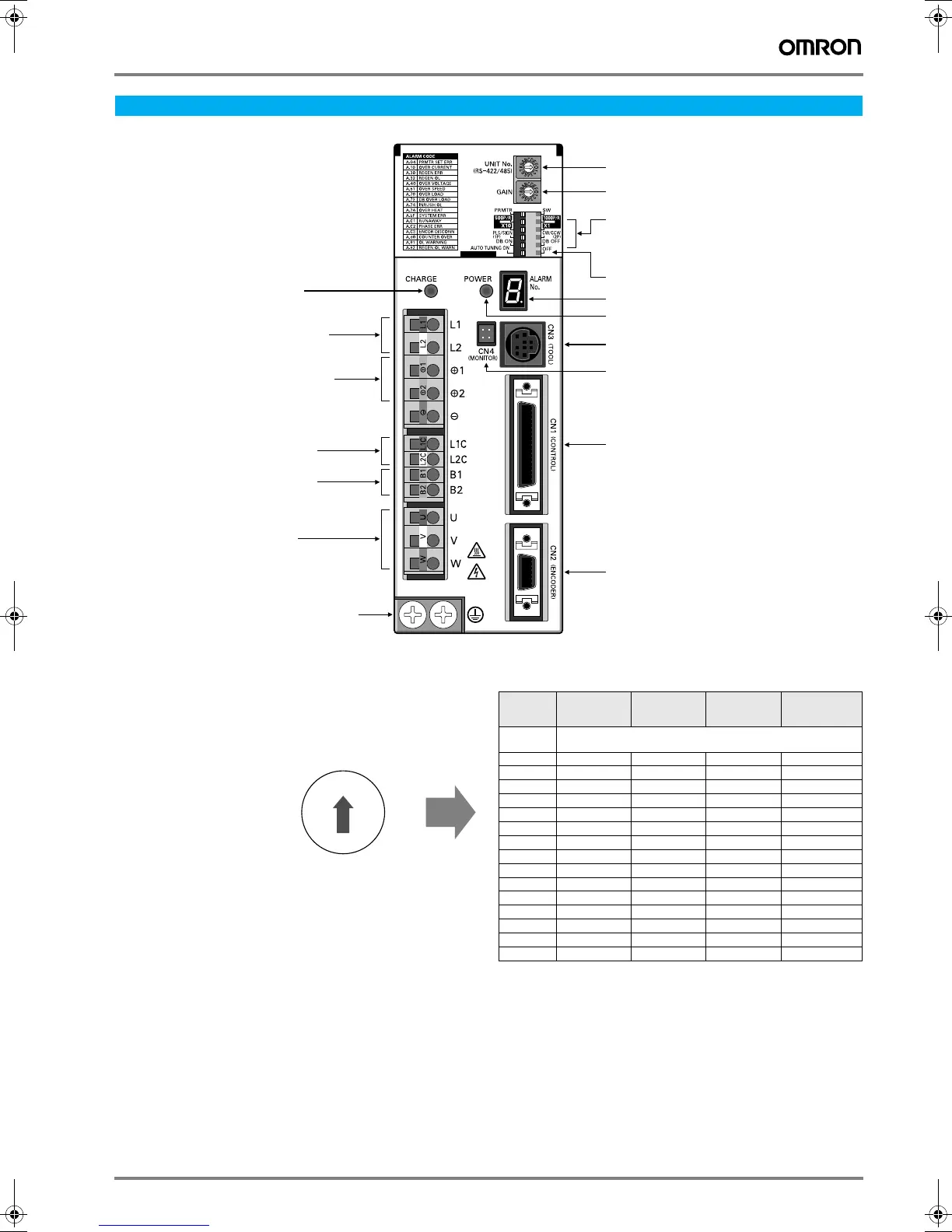
Components
Switch operations
Gain adjustment switch
Adjusts the motor’s responsiveness.
When this switch is set to 0, the unit will operate according to the set-
tings in the internal parameters (Pn100, Pn101, Pn102, and Pn401).
When this switch is set to 1 through F, the unit will operate according to
the rotary switch’s setting.
Decrease the switch setting to lower the motor’s responsiveness
(i.e., so that it moves more smoothly).
Increase the switch setting to raise the motor’s responsiveness
(i.e., so that it moves faster).
Operation
Unit number switch
Gain adjustment switch
DIP switch
Autotuning switch
• Resolution setting
• Command pulse input setting
• Dynamic brake setting
Alarm indicator
Monitor output connector (CN4)
Power indicator
Control I/O connector (CN1)
Communications connector (CN3)
Encoder input connector (CN2)
Charge indicator
Control-circuit power terminals
Main-circuit power terminals
External regeneration
Resistor terminals
DC reactor terminals
Servo motor power terminals
Ground terminals for
power supply and
servo motor power
0
F1
2
Setting Position loop
gain
Speed loop
gain
Speed loop
integral
constant
Torque
command filter
time constant
0 Enables parameter settings
(including settings other than gain settings).
1 15 15 4,000 250
2 20 20 3,500 200
3 30 30 3,000 150
4 40 40 2,000 100
560601,50070
685851,00050
7 120 120 800 30
8 160 160 600 20
9 200 200 500 15
A 250 250 400 10
B 250 250 400 10
C 250 250 400 10
D 250 250 400 10
E 250 250 400 10
F 250 250 400 10
Y203-EN2-02-Katalog.book Seite 157 Mittwoch, 24. Mai 2006 2:22 14