Three, 1.6 dia.
RF min. 0.01 N {1 gf}
(reference value)
0.02 N {2 gf} 0.06 N {6 gf} 0.06 N {6 gf}
OT min. 1.2 mm 1.2 mm 1.2 mm 1.0 mm
MD max. 0.8 mm 0.8 mm 0.8 mm 1.0 mm
FP max. 15.5 mm
OP 10.7±0.8 mm
Note: The values indicated in parentheses are reference values for cases when the installation direction is such that the lever weight is not
applied to the plunger.
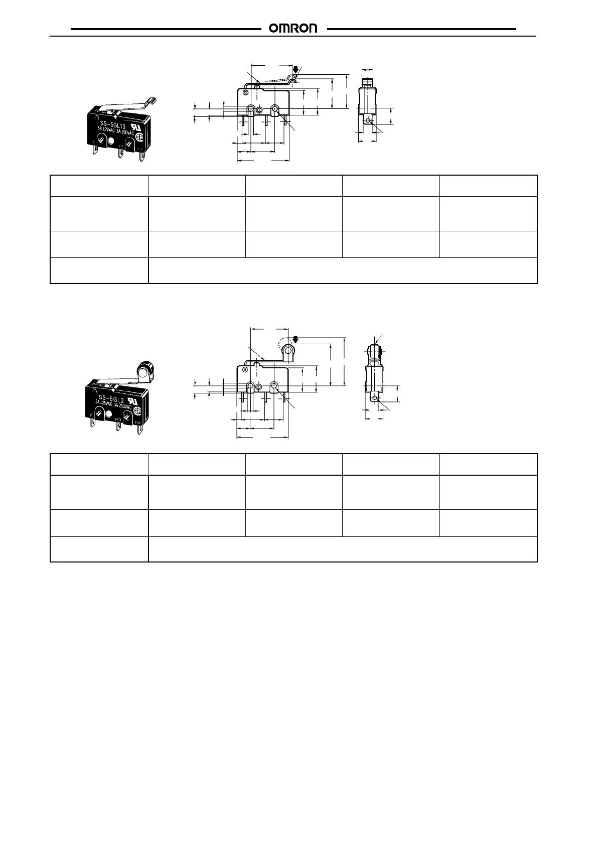
Hinge Roller Lever Models
SS-01GL2(-E, -F)
SS-5GL2(-F)
SS-10GL2
Three, 1.6 dia.
2.35
+0.075
–0.05 dia.
2.35
+0.075
–0.05 dia. holes
4.8 dia. × 3.2
(see note 2)
Note: 1. Stainless-steel spring lever
2. Polyacetal resin roller
2.5±0.07 dia.
t = 0.3
(see note 1)
2.5
2.9
14.5
FP
OP
10.2
9.5
6.4
8.8
7.3
5.1
19.8
3.2
6.4
9.5±0.1
1.6
A
Model SS-01GL2-E SS-01GL2-F
SS-5GL2-F
SS-01GL2
SS-5GL2
SS-10GL2
OF max.
RF min. 0.01 N {1 gf}
(reference value)
0.02 N {2 gf} 0.06 N {6 gf} 0.06 N {6 gf}
OT min. 1.2 mm 1.2 mm 1.2 mm 1.0 mm
MD max. 0.8 mm 0.8 mm 0.8 mm 1.0 mm
FP max. 19.3 mm
OP 14.5±0.8 mm
Note: The values indicated in parentheses are reference values for cases when the installation direction is such that the lever weight is not
applied to the plunger.
 Loading...