!
4-8SectionOffset and Gain Adjustment
96
4. With the voltage or current having been input so that the conversion value
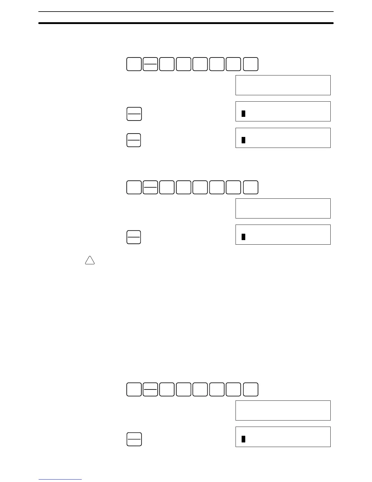
for the Analog I/O Unit is maximized (0FA0 or 07D0), turn bit 04 (the Set Bit)
of IR word n+1 ON and then OFF again.
SHIFT
CONT
#
1
B
0
A
1
B
0
A
4
E
MONTR
10104 10100
^OFF ^ ON
PLAY
SET
10104 10100
ON ^ ON
REC
RESET
10104 10100
OFF ^ ON
While the Gain Bit is ON, the gain value will be saved to the Unit’s EEPROM
when the Set Bit turns ON.
5. To finish the gain adjustment, turn OFF bit 01 (the Gain Bit) of IR word n+1.
SHIFT
CONT
#
1
B
0
A
1
B
0
A
1
B
MONTR
10101 10104
^ ON ^OFF
REC
RESET
10101 10104
OFF ^OFF
Caution Do not turn OFF the power supply or restart the Unit while the Set Bit is ON (data
is being written to the EEPROM). Otherwise, illegal data may be written in the
Unit’s EEPROM and “Special I/O Unit Errors” may occur when the power supply
is turned ON or when the Unit is restarted, causing a malfunction.
When making adjustments, be sure to perform both the offset adjustment and
gain adjustment.
Note The EEPROM can be overwritten 50,000 times.
Follow the procedure outlined below to return the offset and gain adjusted val-
ues to their default settings.
The following example uses input number 1 adjustment for illustration. (The unit
number is 0.)
1, 2, 3... 1. Turn ON bit 05 (the Clear Bit) of IR word n+1. (Hold the ON status.) Regard-
less of the input value, 0000 will be monitored in IR word n+8.
SHIFT
CONT
#
1
B
0
A
1
B
0
A
5
F
MONTR
10105
^OFF
PLAY
SET
10105
ON
Clearing Offset and Gain
Adjusted Values