2-6SectionOffset and Gain Adjustment
29
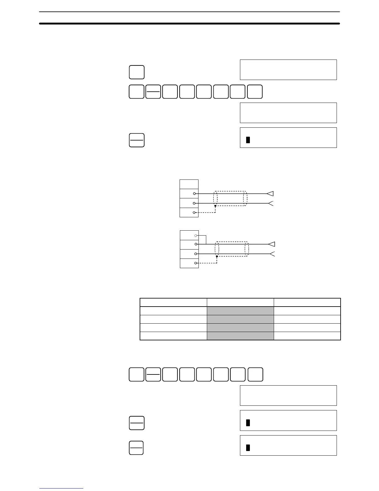
The following example uses input number 1 adjustment for illustration. (The unit
number is 0.)
1, 2, 3... 1. Turn ON bit 00 (the Offset Bit) of IR word n+1. (Hold the ON status.)
CLR
00000
SHIFT
CONT
#
1
B
0
A
1
B
0
A
0
A
MONTR
10100
^OFF
PLAY
SET
10100
ON
The analog input’s digital conversion values while the Offset Bit is ON will be
monitored in IR word n+8.
2. Check whether the input devices are connected.
A0
A1
A2
A3
A0
A1
A2
A3
+
–
+
–
Voltage input
Input 1
Current input
Input 1
3. Input the voltage or current so that the conversion value becomes 0000. The
following table shows the the offset adjustment voltages and currents to be
input according to the input signal range.
Input signal range Input voltage/current Input range
0 to 10 V 0 V –0.5 to 0.5 V
–10 to 10 V 0 V –1.0 to 1.0 V
1 to 5 V 1 V 0.8 to 1.2 V
4 to 20 mA 4 mA 3.2 to 4.8 mA
4. With the voltage or current having been input so that the conversion value
for the Analog Input Unit is 0000, turn bit 04 (the Set Bit) of IR word n+1 ON
and then OFF again.
SHIFT
CONT
#
1
B
0
A
1
B
0
A
4
E
MONTR
10104 10100
^OFF ^ ON
PLAY
SET
10104 10100
ON ^ ON
REC
RESET
10104 10100
OFF ^ ON