14
IR FunctionName
Word Bit
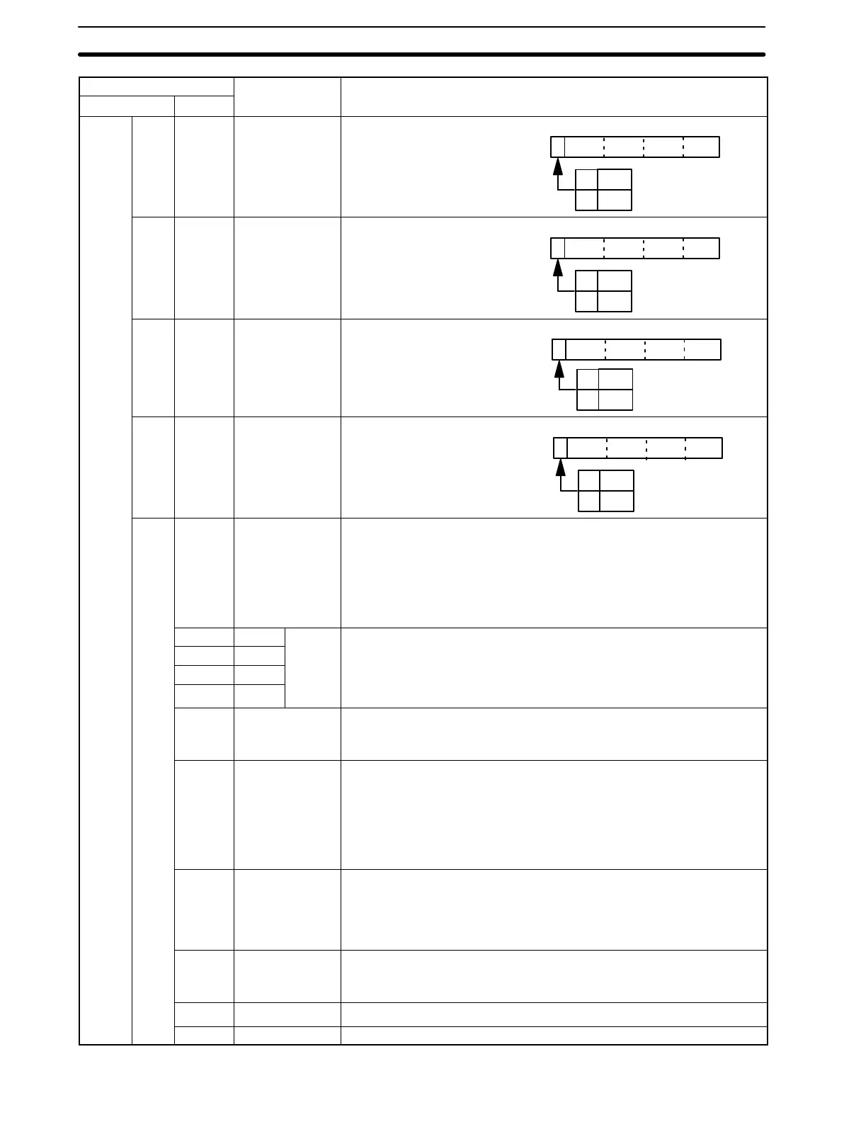
Input n + 1 00
through
15
Input 1
conversion
0
1
+
–
x 10
3
x 10
2
x 10
1
x 10
0
15 00
The temperature input data
of input 1 is displayed in
BCD.
n + 2 00
through
15
Input 2
conversion
0
1
+
–
x 10
3
x 10
2
x 10
1
x 10
0
15 00
The temperature input data
of input 2 is displayed in
BCD.
n + 3 00
through
15
Input 3
conversion
x 10
3
x 10
2
x 10
1
x 10
0
15 00
The temperature input data
of input 3 is displayed in
BCD.
0
1
+
–
n + 4 00
through
15
Input 4
conversion data
0
1
+
–
x 10
3
x 10
2
x 10
1
x 10
0
15 00
The temperature input data
of input 3 is displayed in
BCD.
n + 5 00 Setting Error This bit turns ON when the specified temperature specification code
number (word n bits 08 through 13) results in one of the following: 1) a
figure above 26; or 2) the temperature sensing element corresponds to a
different specified code number than the one actually connected to the
Temperature Sensor Unit. For example, if pin 4 is set for K(CA) and the
temperature specification code number is set to 11-25, a setting error is
generated.
01 Input 1
Discon- If a disconnection is detected in one of the inputs, the bit corresponding
02 Input 2
nection to that particular input turns ON. The conversion data of the word
03 Input 3
de-
tected
corresponding to the disconnected input (words n+1 through n+4)
becomes “E039.”
04 Input 4
tected becomes “E039.”
05 Memory error Whenever an error occurs in the Temperature Sensor’s internal memory
(the memory storing the conversion data from each of the four inputs),
this bit turns ON.
06 Setting standby This bit keeps the setting of the temperature specification code number
on standby. After the temperature specification switch (pin 3) on the back
panel is set to the ON position, and while the power supply is ON or
during Restart, this bit remains ON until the setting is completed. When
setting the temperature specification, turn the temperature specification
setting flag (word n bit 15) ON. Refer to page 17 Temperature
specification setting flag.
07 Data invalid After the power supply is turned ON, or after restart, the conversion data
remains unstable for several seconds; during this period, this bit turns
ON. Once all the data stabilizes, the bit turns OFF. While this bit is OFF,
program with the conversion data from words n+1 through n+3. Refer to
page 21 for conversion data listing.
08
through
13
Temperature
specification
code number
These bits pinpoint the current settings of the temperature specification
code number and represent the confirmation area (00 through 25).
14 --- Not used
15 Running Turns ON while the Unit is operating.
Bit Allocation Section 3-2