!
8
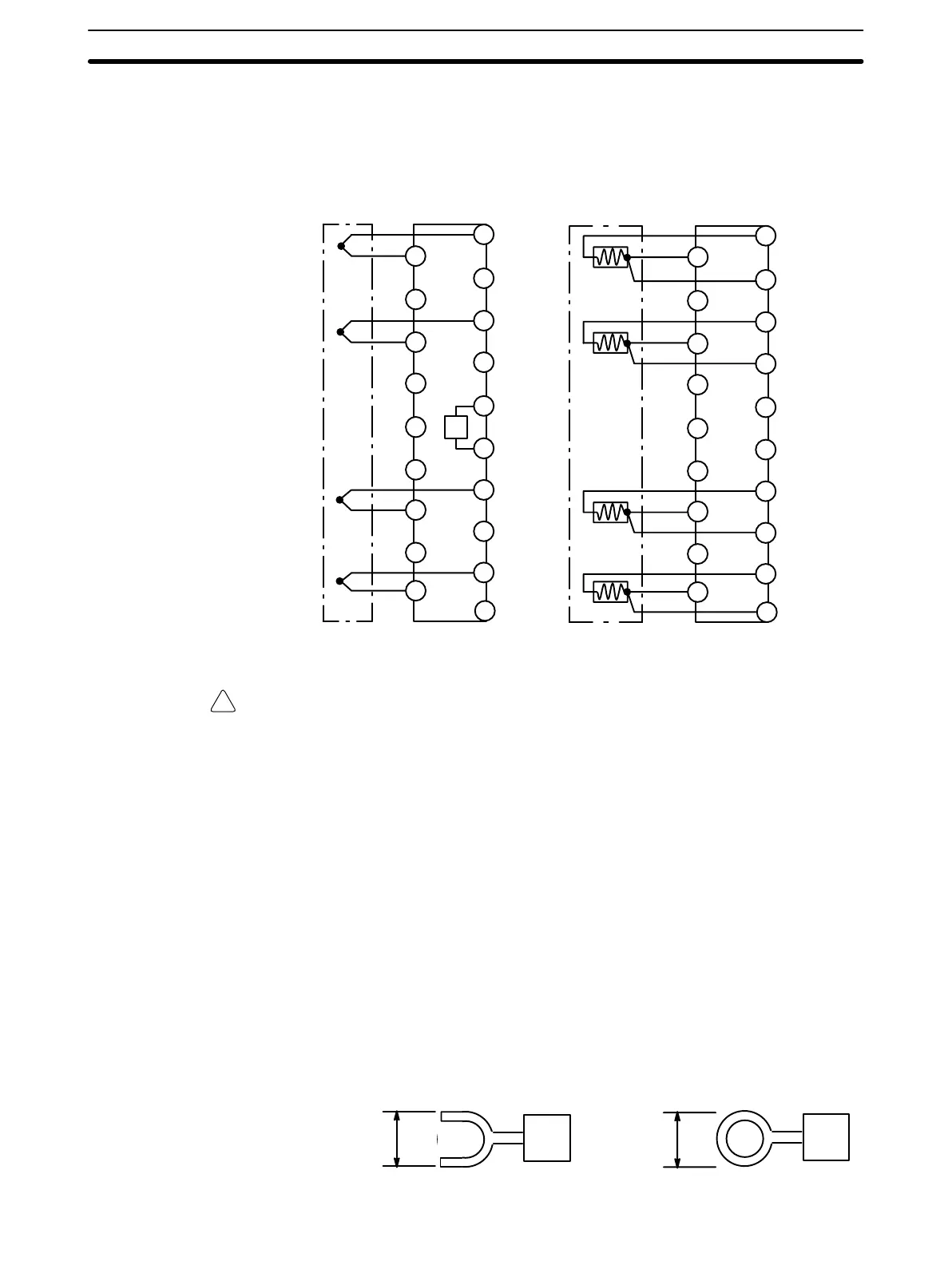
2-1 Setup
External Connections
B0
B1
B4
B5
B6
B7
B8
B3
A1
A2
A3
A4
A5
A6
A7
A8
B2
R
0
A0
+
–
+
–
+
–
+
–
Input 1
Input 2
Input 3
B9
Input 4
B0
B1
B8
B3
B4
B5
B6
B7
A1
A2
A3
A4
A5
A6
A7
A8
B9
B2
A0
Input 1
Input 2
Input 3
Input 4
A
B
B
′
A
B
B′
A
B
B′
A
B
B
′
C200H-TS001/002 C200H-TS101/102
Caution R
0
: Cold-junction compensating resistor
The cold-junction compensating resistor connecting terminals B4 and B5 on the
C200H-TS001/002 is fully integrated in the internal circuitry of the Unit and
serves to maintain accuracy. Be careful not to remove this resistor and be sure
the screws are always tight.
Unused Input Terminals For TS001/002 (thermocouple input), short the positive and negative poles of
the thermocouple inputs (for example, terminals A8 and B8 in Input 4).
For TS101/102 (platinum RTD input), short the B and B′ terminals (for exam-
ple, terminals A8 and B9 for Input 4), and connect a 100 Ω (1/8 W minimum)
resistor between terminals A and B. (For example, A8 and B8 for input 4.)
Removable Terminal Block Connections
When Using Solderless Crimp Leads
Use M3.5 screws (with self-rising pressure plates) for mounting solderless
crimp terminals.
7 mm max.
7 mm max.
Setup Section 2-1