9
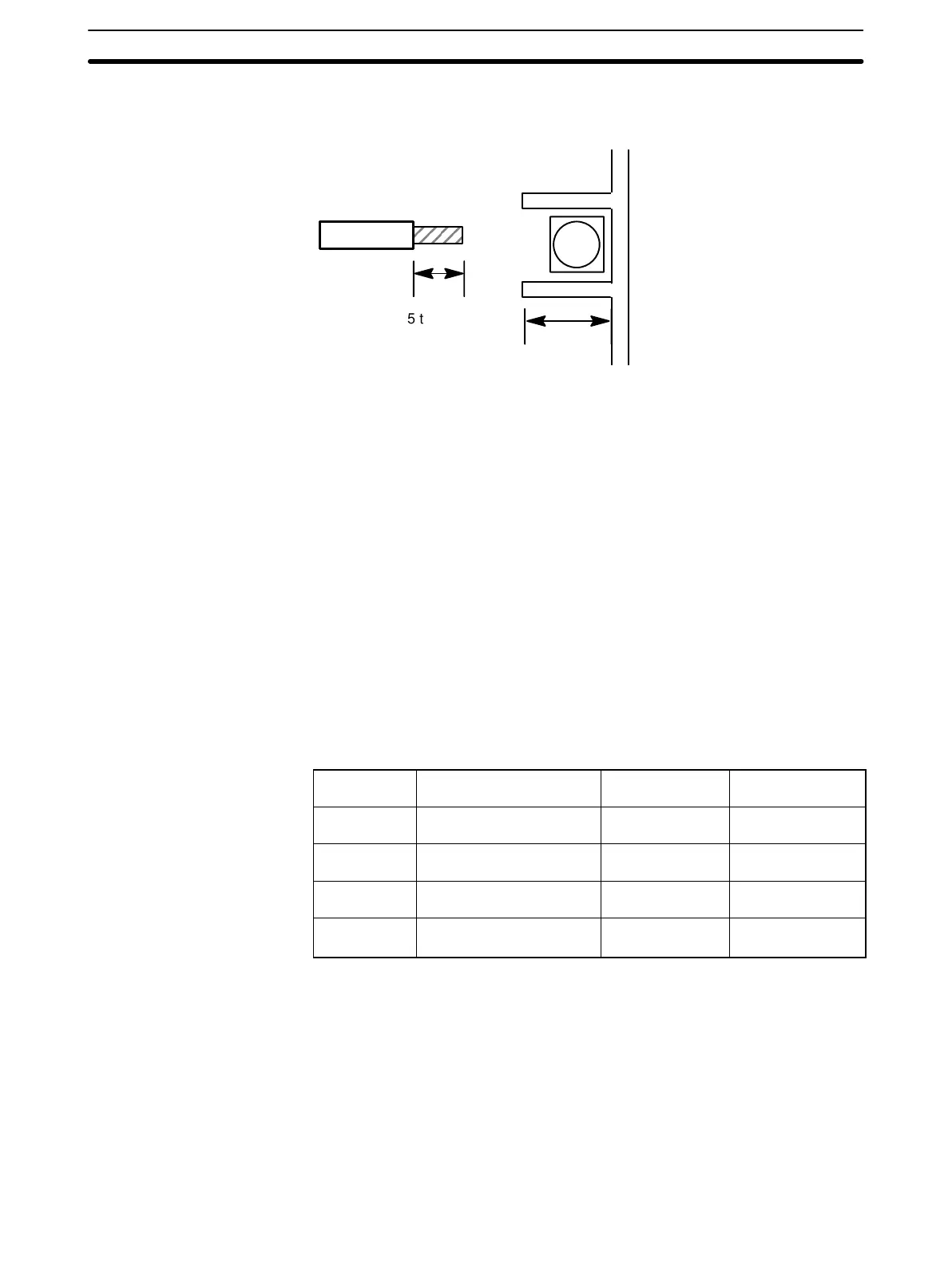
Soldered leads
Carefully tin the 5- to 7-mm exposed end of the lead wire.
+
5 to 7 mm
10 mm
Tighten the screws to a
torque of 0.8 N S m.
Wiring Notes To avoid influence from induced noise, keep the input signal wires (compen-
sating wires or lead wires) away from the power source line or load line by at
least 300 mm. Also be sure not to lay them parallel to, or in the same cable
as, the power line. Using shield wires in separated ducts or pipes is also an
effective way to reduce influence from noise. Attach surge absorbers or noise
filters to peripheral devices that generate noise (in particular, devices that
possess inductance components, such as motors, transistors, solenoids, or
magnet coils). Install away from devices that generate strong, high-frequency
waves or that generate surges.
Connect the thermocouples with the compensating wires as shown in the
following diagram. Connect platinum RTDs with lead wires of low resistance
(for example, copper wires). Make the three lead wires extending from the
platinum RTDs equal in length. Do not short-circuit the B wire and B’ wire
near the terminal block connector, because it causes measurement errors.
Input Signal Wire Extension The input signal wire should be as short as possible so that the effect of out-
side noise is minimized. The following table has more information on type
and length of the signal wire.
Sensor-Input Wire Configuration Maximum
Extension Length
K (CA) Compensating conductor
WX-H, WX-H6
0.3 mm
2
x 7 leads 80 m
J (IC) Compensating conductor
JX-H, JX-H6
0.3 mm
2
x 7 leads 70 m
L (Fe-CuNi) Compensating conductors
JX
0.3 mm
2
x 7 leads 70 m
JPt 100 ΩPt
100
Ω
Copper wire 0.5 mm
2
120 m
Setup Section 2-1