2
1–1 Nomenclature
This section gives the names and functions of the various components of
K–Type PCs and the basic Units with which they can be combined in a
System.
1–1–1 CPUs
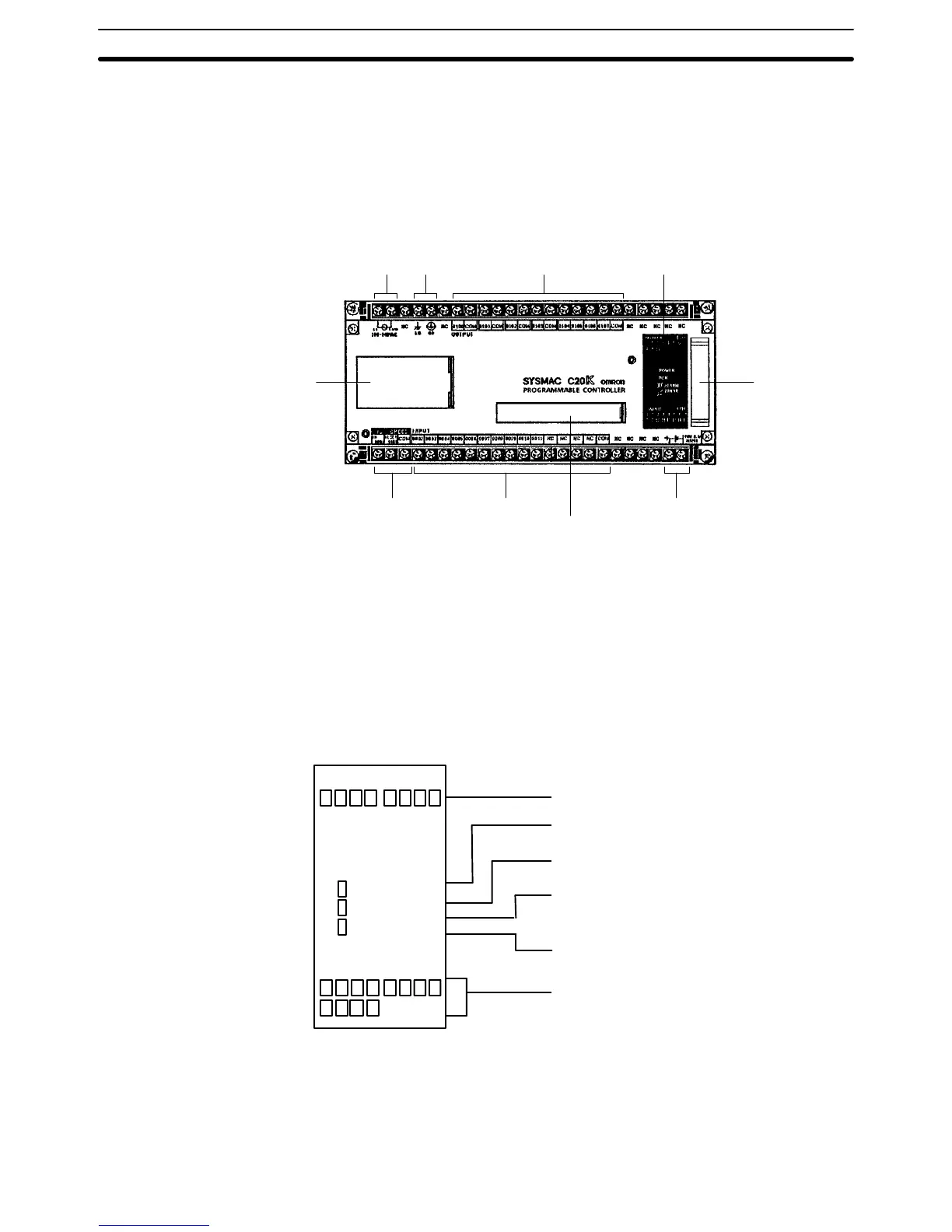
In the diagram below, the C20K is shown as a representative model. Refer to
Appendix A Standard Models for your model’s exact specifications.
Power supply Ground Outputs Indicators
Expansion
I/O Unit,
Analog
Timer Unit, or
I/O Link Unit
connector
24–VDC output
Peripheral connector
InputsHigh–speed counter
(HDM) inputs
EP–ROM socket,
DIP switch
High–speed Counter When the high–speed counter (HDM(61)) is not being used, the two high–
speed counter input terminals can be used as normal DC input terminals.
Their ON/OFF response time, however, will be shorter (0.15 ms max.). Re-
gardless of whether or not the high–speed counter command is being used,
DIP switch pins 7 and 8 must be off whenever the hardware reset is not be-
ing used.
Indicators The diagram below shows the functions of the various indicators, taking the
C20K as an example.
8 9 10 11
0 1 2 3 4 5 6 7
OUTPUT 1 CH
POWER
RUN
ALARM
ERROR
INPUT 0 CH
OUTPUT: Shows whether the output is ON or OFF.
POWER: Stays lit while power is turned on to the
PC.
RUN: Stays lit while the PC is operating normally.
ALARM: Blinks during battery abnormality or cycle
time overrun. At this time PC operation will be
intermittent.
ERROR: Lights when self–diagnosis detects an
abnormality. The PC will stop operating.
INPUT: Shows whether the input is ON or OFF.
0 1 2 3 4 5 6 7
Memory Each of the C–Series K–Type PCs is provided with a built–in RAM (random–
access memory), as well as a ROM (read–only memory) chip socket. Either
may be used with ease. It is recommended to use the RAM for programming
and, when the program is completed, to save it in a ROM chip for protection.
The memory capacity in either case is 1,194 addresses.
Nomenclature Section 1–1