49
2. Turn OFF the power to the I/O Link Unit.
3. Check to be sure that the power supply LED light is off. Remove the
cover on the side panel of the Unit, using a screwdriver if necessary.
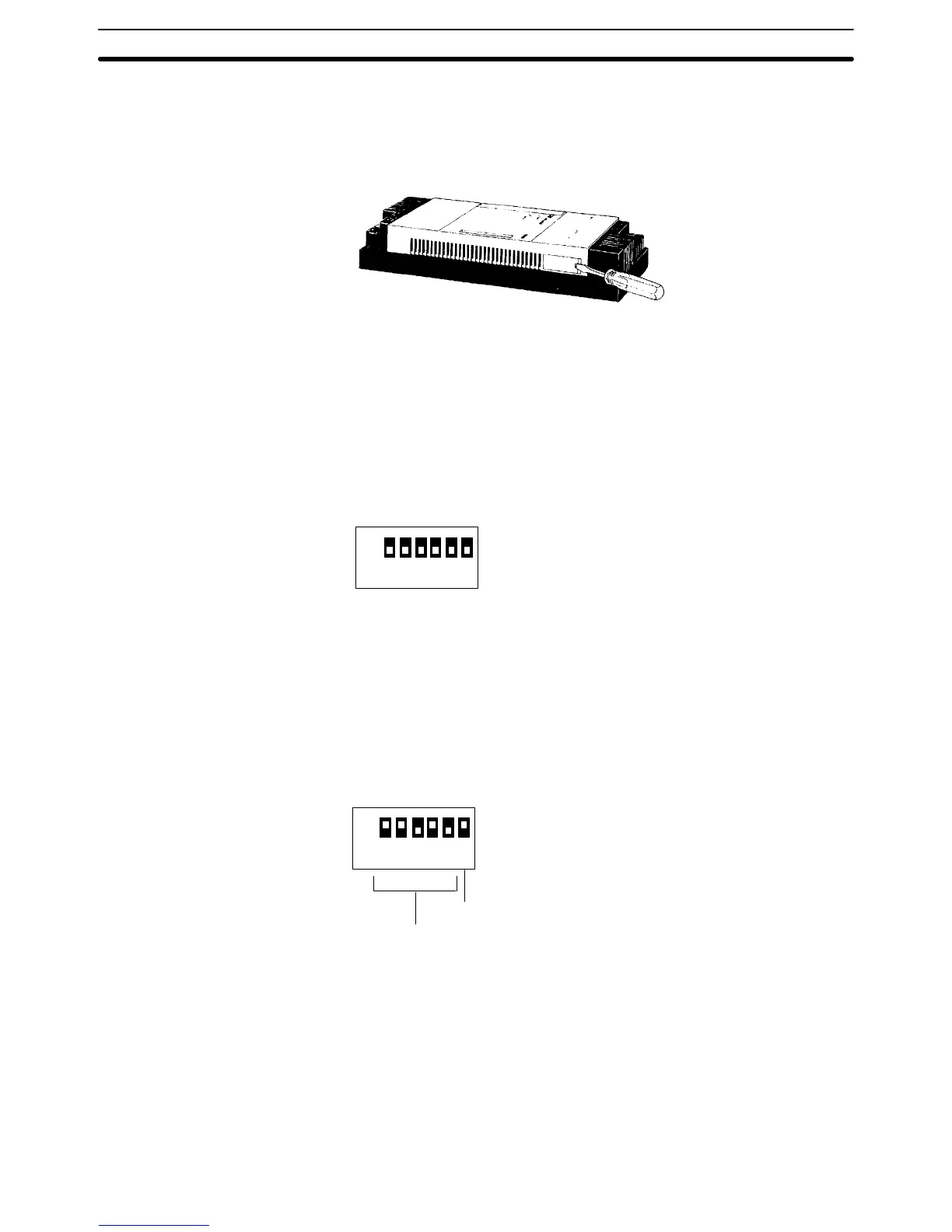
4. Use the 6 DIP switch pins to set the word address from 0 to 30. As
shown in the diagram below, the word addresses are set in binary, with
pin 5 being “1” and pin 1 being “16.” Beginning with pin 1, turn ON the
pins required to arrive at the desired words. Turn ON pin 6 to set the
termination resistance if the I/O Link Unit is a terminator (the final Unit in
the System). If the Unit is not a terminator, leave pin 6 OFF.
ON
123456
168421
The following example diagram illustrates the proper DIP switch setting for IR
26. In C200H/C1000H/C2000H Remote I/O Systems, the word actually as-
signed to the I/O Link Unit may vary from the switch setting. Refer to the Re-
mote I/O System Manual for details.
ON
1 234 56
16 8 4 2 1
Terminator: ON
Pins 1, 2, and 4, set ON
16 + 8 + 2 =IR 26
5. After initially setting the DIP switches, an I/O table check should be per-
formed on the CPU to ensure that there are no errors in the settings.
6. Replace the cover. In addition, to prevent dirt or outside light from caus-
ing a malfunction, be sure that any unused optical fiber connectors are
covered with the protective caps. The Unit should be ready to operate
as soon as power is turned on. If it does not operate normally, refer to
3-2 Self-diagnostic Function.
Switch Settings
Section 2-8