Varispeed F7 279
Control circuite
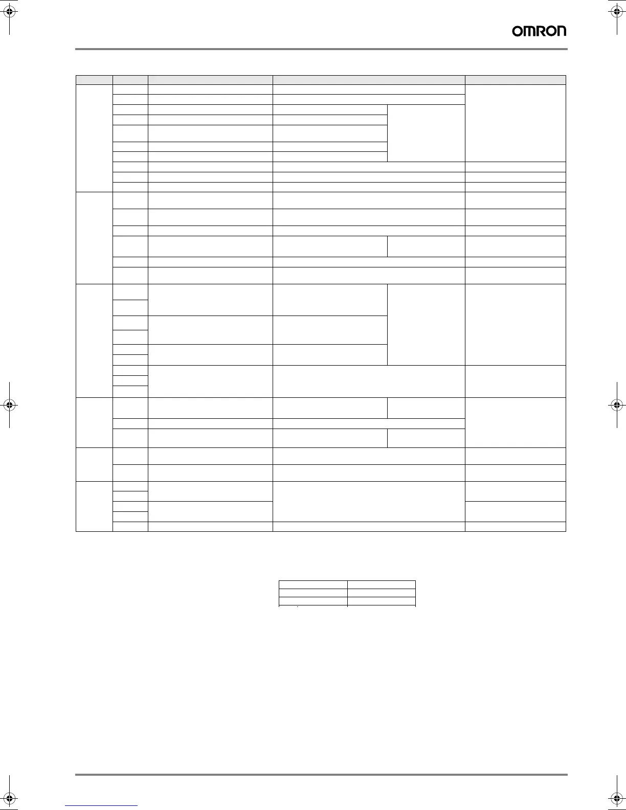
Type No. Signal name Function Signal level
Digital input signals
S1
Forward run/stop command Forward run when ON; stopped when OFF. 24 VDC, 8 mA
photocoupler
S2
Reverse run/stop command Reverse run when ON; stopped when OFF.
S3
External fault input
1
Fault when ON. Functions are selected by
setting H1-01 to H1-05.
S4
Fault reset
1
Reset when ON
S5
Multi-step speed reference 1
1
(master/auxiliary switch)
1. The default settings are given for terminals S3 to S7. For a 3-wire sequence, the default settings are a 3-wire sequence for S5, multi-step speed setting
1 for S6 and multi-step speed setting 2 for S7.
Auxiliary frequency reference
when ON.
S6
Multi-step speed reference 2
1
Multi-step setting 2 when ON.
S7
Jog frequency reference
1
Jog frequency when ON.
SC
Digital input common – –
SN
Digital input neutral – –
SP
Digital input power supply +24 VDC power supply for digital inputs 24 VDC, 250 mA max.
2
2. Do not use this power supply for supplying any external equipment.
Analog input signals
+V
15 V power output 15 V power supply for analog references 15 V
(max. current: 20 mA)
-
V
-15 V power output -15 V power supply for analog references -15 V
(max. current: 20 mA)
A1
Frequency reference -10 to +10 V/100% -10 to +10 V(20 kΩ)
A2
Multi-function analog input 4 to 20 mA/100%
-10 V to +10 V/100%
Function is selected by
setting H3-09.
4 to 20 mA(250 Ω)
-10 V to +10 V(20 kΩ)
AC
Analog reference common – –
E(G)
Shield wire, optional ground line
connection point
––
Sequence output signals
M1
Running signal
(1NO contact)
Operating when ON. Multi-function contact
outputs
Relay contacts
Contact capacity:
1 A max. at 250 VAC
1 A max. at 30 VDC
3
M2
M3
Zero speed Zero level (b2-01) or below when ON
M4
M5
Speed agreement detection Within ±2 Hz of set frequency when
ON.
M6
MA
Fault output signal Fault when CLOSED across MA and MC
Fault when OPEN across MB and MC
Relay contacts
Contact capacity:
1 A max. at 250 VAC
1 A max. at 30 VDC
3
3. When driving a reactive load, such as a relay coil with DC power supply, always insert a flywheel diode.
MB
MC
Analog output
signals
FM
Multi-function analog output
(frequency output)
0 to 10 V, 10V=100% output
frequency
Multi-function
analog output 1
-10 to +10 V max. ±5%
2 mA max.
4 to 20 mA current output
AC
Analog common –
AM
Multi-function analog output
(current monitor)
0 to 10 V, 10V=200% inverter's rated
current
Multi-function
analog output 2
Pulse I/O
RP
Pulse input
4
4. Pulse input specifications are given in the following table.
H6-01 (frequency reference input) 0 to 32 kHz (3 kΩ)
High level voltage 3.5 to 13.2 V
MP
Pulse monitor H6-06 (output frequency) 0 to 32 kHz
+15 V output (2.2 kΩ)
RS-485/422
R+
MEMOBUS communications input For 2-wire RS-485, short R+ and S+ as well as R- and S-. Differential input,
photocoupler isolation
R-
S+
MEMOBUS communications output Differential input,
photocoupler isolation
S-
IG
Signal common – –
Low level voltage 0.0 to 0.8 V
High level voltage 3.5 to 13.2 V
H duty 30% to 70%
Y203-EN2-02-Katalog.book Seite 279 Mittwoch, 24. Mai 2006 2:22 14

 Loading...


