278 Frequency inverters
Main circuit
Voltage 200 V 400 V
Model CIMR-F7Z 20P4 to 2018 2022, 2030 2037 to 2110 40P4 to 4018 4022 to 4055 4075 to 4300
Max. applicable motor output 0.4 to 18.5 kW 22 to 30 kW 37 to 110 kW 0.4 to 18.5 kW 22 to 55 kW 75 to 300 kW
R/L1
Main circuit input
power supply
Main circuit input
power supply
R-R1, S-S1 and T-T1 have been wired
before shipment (See P59).
Main circuit input
power supply
Main circuit input power supply
R-R1, S-S1 and T-T1 have been wired
before shipment
S/L2
T/L3
R1/L11
--- ---
S1/L21
T1/L31
U/T1
Inverter output Inverter output
V/T2
W/T3
B1
Braking resistor unit ------ Braking resistor unit ------
B2
•DC reactor
(1- 2)
•DC power supply
1
(1 - )
1.
1 - DC power input does not conform to UL/c-UL listed standard.
•DC power supply
(1- 2)
1
•Braking unit
(3 - )
•DC reactor
(1- 2)
•DC power supply
1
(1 - )
•DC power supply
(1- 2)
1
•Braking unit
(3 - )
1
2
3
--- ---
/l
2
------
Cooling fan power
supply
2
2. Cooling fan power supply r/l
1
- /l
2
: 200 to 220 VAC 50 Hz, 200 to 230 VAC 60 Hz
(A transformer is required for 230 V 50 Hz or 240 V 50/60 Hz power supply.)
---
r/
l
1
---
Cooling fan power
supply
3
3. Cooling fan power supply r/l
1
- 200 / l
2
200: 200 to 220 VAC 50 Hz, 200 to 230 VAC 60 Hz, r/l
1
- 400 / l
2
400: 380 to 480 VAC 50/60 Hz
200 / l
2
200
------
400 / l
2
400
Ground terminal (100 Ω or less) Ground terminal (10 Ω or less)
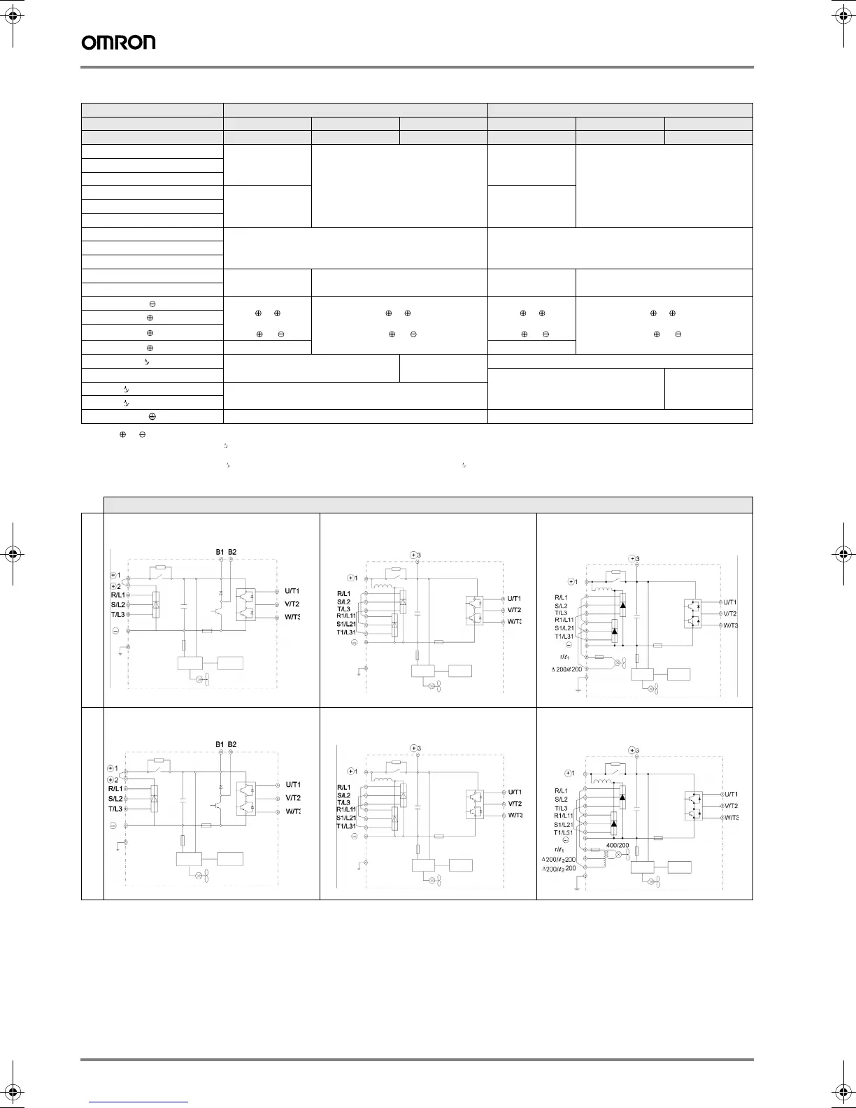
Main circuit configuration
200 V class400 V class
-
o
CIMR-F7Z2022, 2030
CIMR-F7Z2037 to 2110
-
o
CIMR-F7Z4022 to 4055
CIMR-F7Z4075 to 4300
Y203-EN2-02-Katalog.book Seite 278 Mittwoch, 24. Mai 2006 2:22 14

 Loading...


