XtraDrive 125
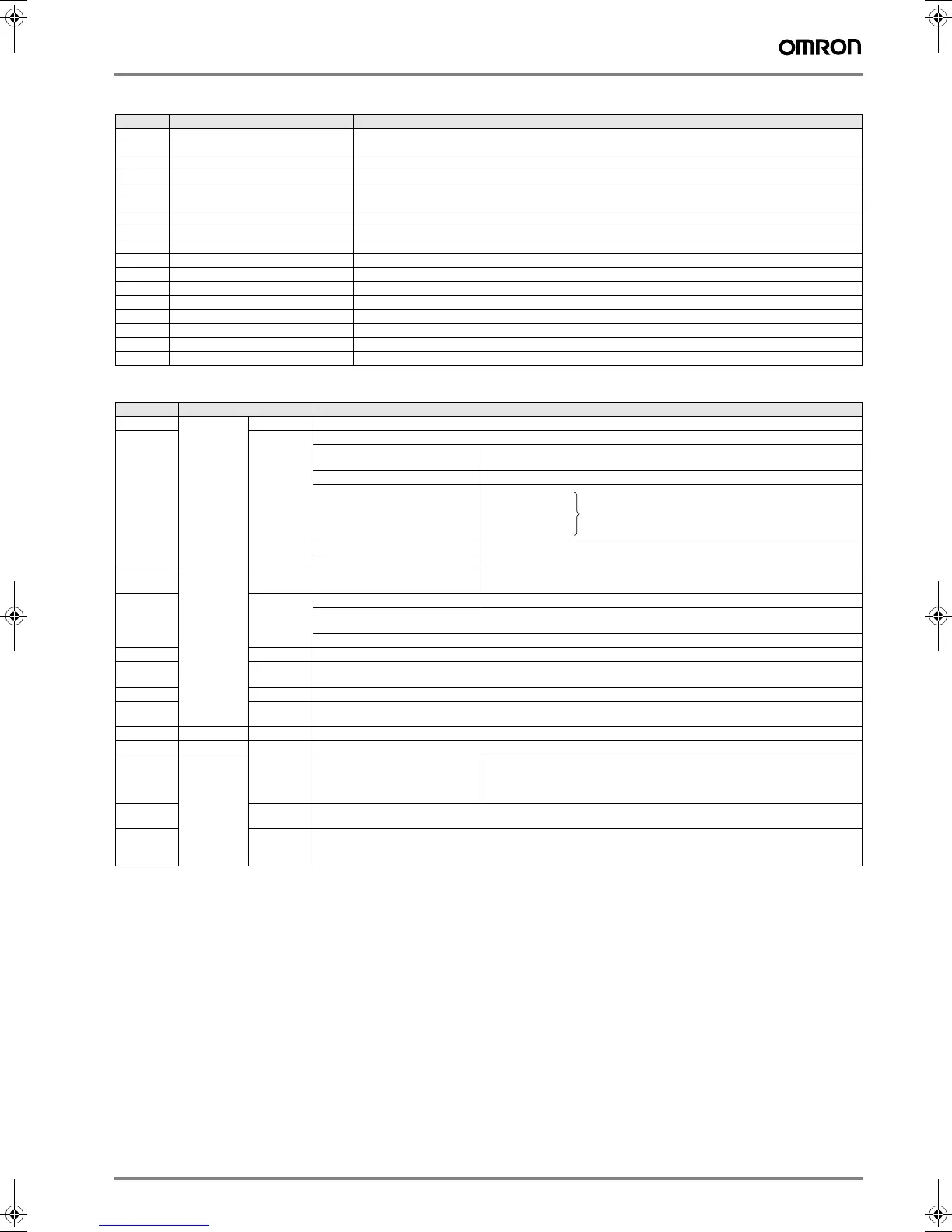
Encoder connector (CN2)
I/O signals (CN1) - input signals
Note: 1. Pin numbers in parentheses () indicate signal grounds.
2. The functions allocated to /S-ON, /P-CON. P-OT, N-OT, /ALM-RST, /P-CL, and /N-CL input signals can be changed by using the
parameters.
3. The voltage input range for speed and torque references is a maximum of ±12 V.
Pin Symbol Function
1, 2, 3 PPG0V Encoder power supply GND
4, 5, 6 PPG5V Encoder power supply +5 V
7- -
8 PS+ Encoder serial signal input
9PS− Encoder serial signal input
10 SePG5V Serial encoder power supply +5 V (Sigma-II)
11 SePG0V Serial encoder power supply GND (Sigma-II)
12 BAT+ Battery + (used only with absolute encoder)
13 BAT- Battery - (used only with absolute encoder)
14 PC+ Encoder + C-phase input
15 PC− Encoder − C-phase input
16 A+ Encoder + A-phase input
17 A− Encoder − A-phase input
18 B+ Encoder + B-phase input
19 B− Encoder − B-phase input
20 - -
Shell FG Cable shield ground
Pin No. Signal Name Function
40 Common /S
-
ON Servo ON: Turns ON the servo motor when the gate block in the inverter is released.
41 /P
-
CON Function selected by parameter.
Proportional control reference Switches the speed control loop from PI (proportional/ integral) to P (proportional)
control when ON.
Direction reference With the internal set speed selected: switch the rotation direction.
Control mode
switching
Zero-clamp reference Speed control with zero-clamp function: referencevspeed is zero when ON.
Reference pulse block Position control with reference pulse stop: stops reference pulse input when ON.
42
43
P
-
OT
N
-
OT
Forward run prohibited
Reverse run prohibited
Overtravel prohibited: stops servo motor when movable part travels beyond the
allowable range of motion.
45
46
/P
-
CL
/N
-
CL
Function selected by parameter.
Forward external torque limit ON
Reverse external torque limit ON
Current limit function enabled when ON.
Internal speed switching With the internal set speed selected: switches the internal speed settings.
44 /ALM
-
RST Alarm reset: releases the servo alarm state.
47 +24VIN Control power supply input for sequence signals: users must provide the +24 V power supply.
Allowable voltage fluctuation range: 11 to 25 V
4 (2) SEN Initial data request signal when using an absolute encoder.
21
22
BAT (+)
BAT (-)
Connecting pin for the absolute encoder backup battery.
Do not connect when a battery is connected to the host controller.
5 (6) Speed V
-
REF Speed reference speed input: ±2 to ±10 V/rated motor speed (input gain can be modified using a parameter.)
9 (10) Torque T
-
REF Torque reference input: ±1 to ±10 V/rated motor torque (input gain can be modified using a parameter.)
7
8
11
12
Position PULS
/PULS
SIGN
/SIGN
Reference pulse input
for line driver only
Input mode is set from the following pulses.
Sign + pulse string
CCW/CW pulse
Two-phase pulse (90° phase differential)
15
14
CLR
/CLR
Positional error pulse clear input: clears the positional error pulse during position control.
3
13
18
PL1
PL2
PL3
+12 V pull-up power is supplied when PULS, SIGN, and CLR reference signals are open-collector outputs
(+12 V power supply is built into the SERVOPACK).
Position speed
Position
torque
Torque speed
Enables control mode switching.
↔
↔
↔
Y203-EN2-02-Katalog.book Seite 125 Mittwoch, 24. Mai 2006 2:22 14