124 AC servo systems
General specifications
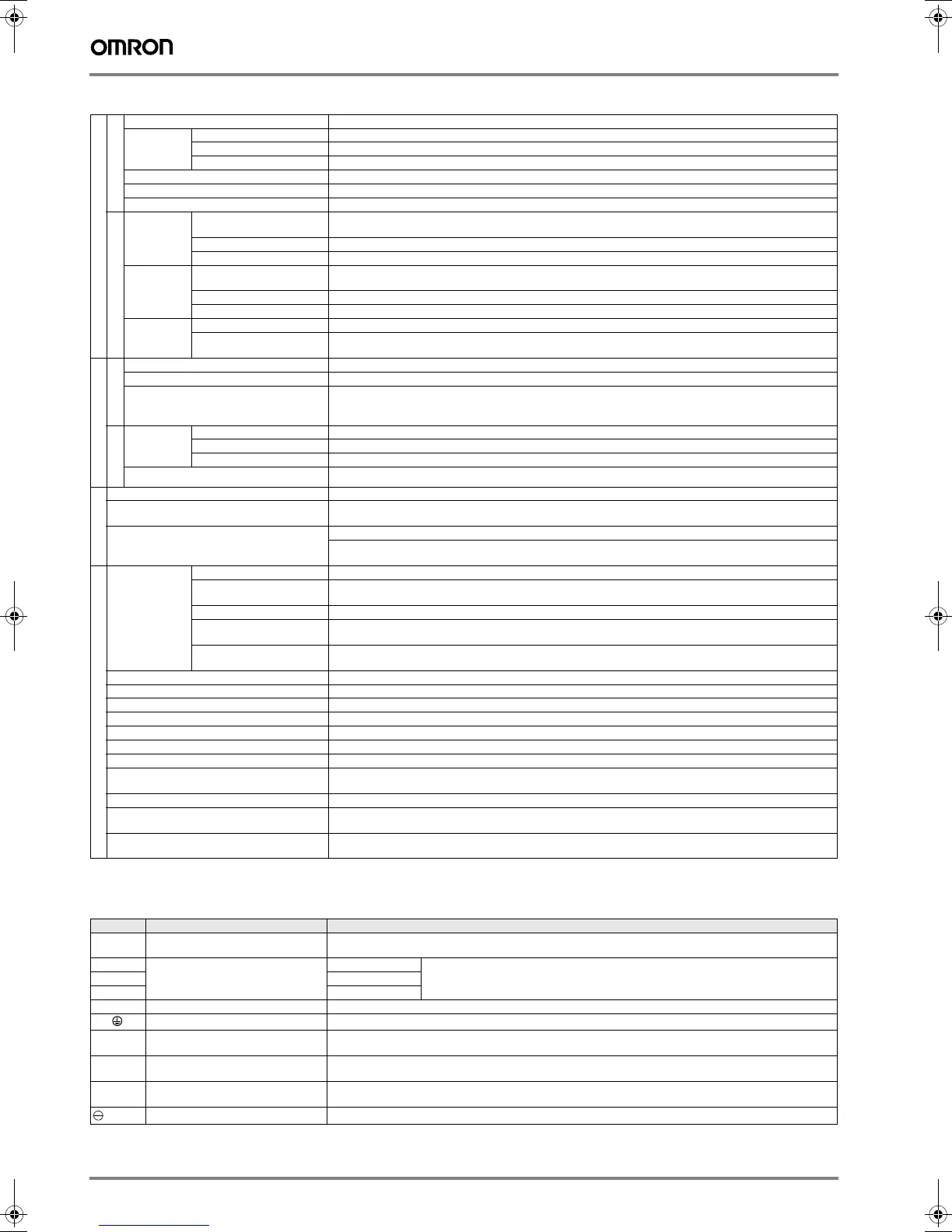
I/O specifications
Terminal specifications
Speed/torque control mode
Performance
Speed control range 1:5000
Speed
variance
Load variance During 0 to 100% load ±0.01% max. (at rated speed)
Voltage variance Rated voltage ±10%: 0% (at rated speed)
Temperature variance 25 ±25 °C: ±0.1 % max (at rated speed)
Frequency characteristics 400Hz (at J
L
= J
M
)
Torque control accuracy (reproducibility) ±2%
Soft start time setting 0 to 10s (acceleration, deceleration can each be set.)
Input signal
Speed
reference
input
Reference voltage ±6VDC (forward motor rotation if positive reference) at rated speed: Set at delivery
Variable setting range: ±2 to ±10 VDC at rated speed/ max. input voltage: ±12 V
Input empedance Approx. 14 kΩ
Circuit time constant -
Torque
reference
input
Reference voltage ±3 VDC (forward rotation if positive reference) at rated speed: Set at delivery
Variable setting range ±1 to ±10 VDC at rated torque reference
Imput impedance Approx. 14 KΩ
Circuit time constant Approx. 47 µs
Contact
speed
reference
Rotation direction selection With P control signal
Speed selection With forward/reverse current limit signal (speed 1 to 3 selection), servo motor stops or another control method is
used when both are OFF.
Position control mode
Performance
Bias Setting 0 to 450 min
-1
(setting resolution: 1 min
-1
)
Feed forward compensation 0 to 100 % (setting resolution: 1%)
Position completed width setting 0 to 250 command units (setting resolution: 1 command unit)
Input signal
Command
pulse
Input pulse type Sign + pulse train, 90° phase displacement 2-phase pulse (A-phase+ B-phase) or CCW/CW pulse train
Input pulse form Line driver (+5 V level) , open collector (+5 V or +12 level)
Input pulse frequency 0 to 500 Kpps (200 Kpps max. at open collector)
Control signal Clear signal (input pulse is same as reference pulse)
I/O signal
Position signal output A-phase, B.phase, C-phase, (S-phase): line driver output S-phase is for absolute encoder only.
Sequence input signal Servo ON, P control (or control mode switching, zero clamp, command pulse inhibit), forward/reverse run
prohibit, alarm reset, forward/ reverse current limit (or internal speed switching)
Sequence output signal Servo alarm, alarm codes (3-bit output): CN1 output terminal is fixed
It is possible to output three types of signals form among: positioning complete (speed agree), motor rotation,
servo ready, current limit, speed limit, brake release, warning, NEAR, and zero point pulse signal
Integrated functions
Communications Interface Digital operator (hand- held type), RS-422 port for PCs, etc. (RS-232C ports under some conditions)
1:N communications N may equal up to 14 when an RS-422A port is used.
CompoWay/F protocol is supported on firmware version "3.20C" and higher
Axis address setting Set by user setting
Functions Status display, user constant setting monitor display, alarm traceback display, JOG run /autotuning operations,
and graphing functions for speed/torque command signal, etc
PROFIBUS (Only models with PROFIBUS) PROFIBUS DP slave, node address 0-125 set by rotary switches, baud rate from
9.6 kbps to 12 Mbps. LED Indicators: Bus failure and system failure
Auto tuning function Position speed loop gain and integral time constant can be automatically set.
Dynamic brake (DB) Operates during main power OFF, servo alarm, servo OFF or overtravel
Regenerative processing Regenerative resistor externally mounted (option)
Overtravel (OT) prevention function DB stop, deceleration stop or coast to stop during P-OT, N-OT operation
Encoder divider function Optional division possible
Electronic gearing 0,01< A/B<100
Internal speed setting function 3 speeds may be set internally
Protective functions Overcurrent, overvoltage, insufficient voltage, overload, main circuit sensor error, heatsink overheat, power phase
loss, overflow, overspeed, encoder error, runaway, CPU error, parameter error, etc.
Analog monitor functions for supervision Integrates analog monitor connectors for supervision of the speed and torque reference signals, etc.
Display functions CHARGE, POWER, 7-segments LEDx5
(Integrated digital operator function, not available in models with PROFIBUS)
Others Reverse connection, zero search, automatic motor discrimination function, and DC reactor connection terminal
for high frequency power suppression function (except: 6 to 15 kW)
Symbol Name Function
L1, L2 or
L1, L2, L3
Main circuit AC input terminal AC power input terminals for the main circuit
U Servo motor connection terminal Red Terminals for outputs to the servo motor.
V White
WBlue
L1C, L2C Control power input terminal AC power input terminals for the control circuit.
Frame ground Ground terminal. Ground to a maximum of 100 Ω. (class 3)
B1, B2 or
B1, B2, B3
Main circuit DC output terminal 5 kW or less: Connect an external regenerative resistor if regenerative energy is high.
5.5 kW: There is no internal regenerative resistor. Be sure to connect an external regenerative resistor unit.
⊕1, ⊕2 DC reactor connection terminal for sup-
pressing power supply harmonic waves
Normally, short ⊕1 and ⊕2. If a countermeasure against power supply harmonic waves is needed,
connect a DC reactor between ⊕1 and ⊕2.
⊕ Main circuit DC output terminal (+) Normally, not connected.
This terminal exists on the servo drives with a capacity opf 6.0 kW or higher only.
Main circuit DC output terminal (n-) Normally, not connected.
Y203-EN2-02-Katalog.book Seite 124 Mittwoch, 24. Mai 2006 2:22 14
 Loading...


