General-purpose Basic Switch Z F-181
Limit
Switches
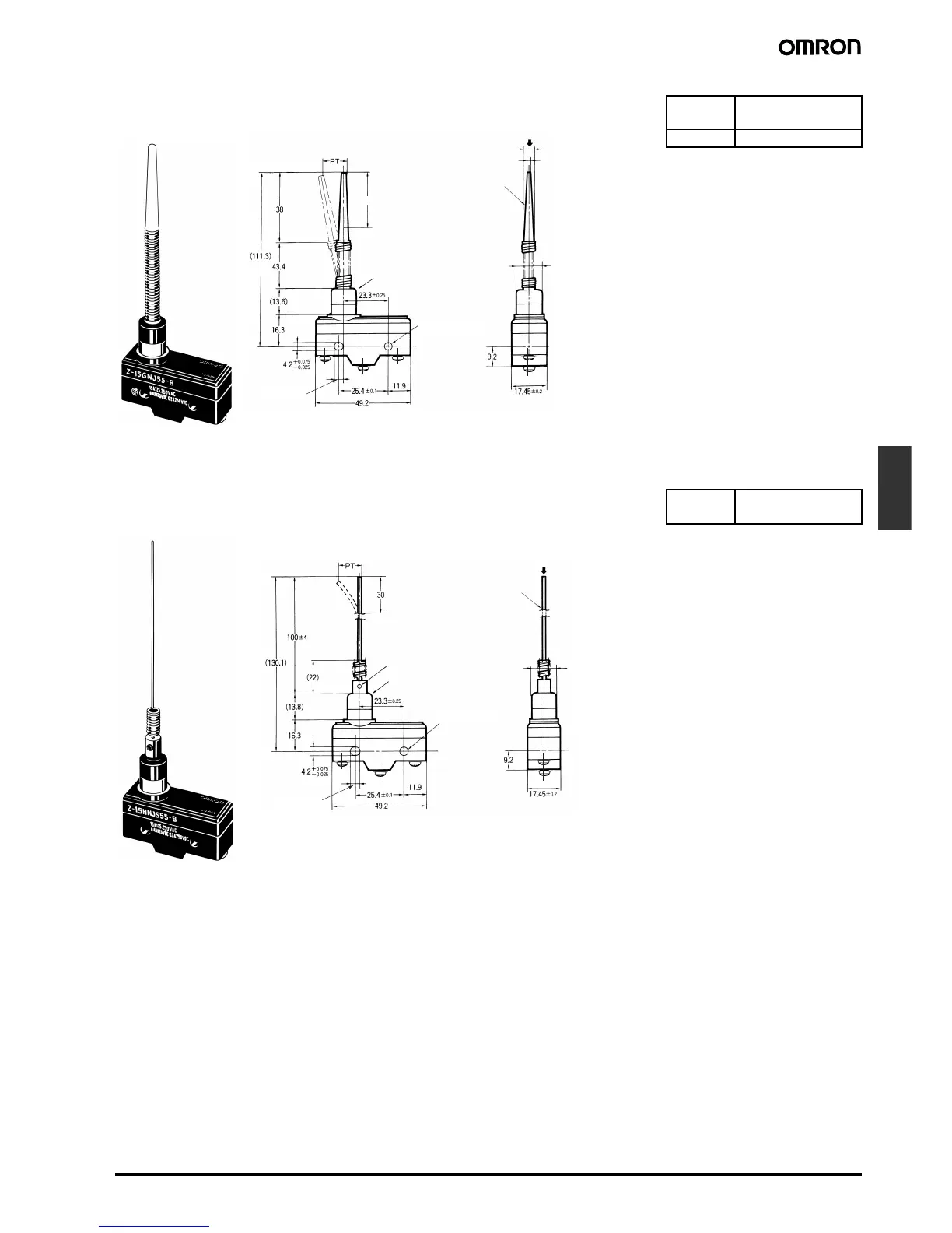
Note: 1. Operation is possible in any direction other than the axial direction (indicated by the arrow ↓).
2. Use only the area within the top 30 mm of the rod as the operating part. (Do not use the area that falls within 80 mm from the mounting
hole as the operating part. Using this area may cause damage to the nylon rod.)
Note: 1. Operation is possible in any direction other than the axial direction (indicated by the arrow ↓).
2. Use only the area within the top 30 mm of the rod as the operating part. (Do not use the area that falls within 100 mm from the mounting
hole as the operating part. Using this area may cause damage to the steel wire.)
3. The steel wire can be replaced if damaged. (Model: Lever for HNJS55)
OF max.
PT max.
0.49 N {50 gf}
(20 mm)
OT 42 to 60 mm
OF max.
PT max.
0.15 N {15 gf}
(25 mm)
Flexible Rod (Coil Spring)
Z-15GNJ55-B
4.2
+0.075
dia. hole
−0.025
30 Operating range (see note 2)
Nylon rod
Rubber cap
6.1 dia.
3.2 dia.
12 dia.
(see note 1)
4.36
+0.1
dia.
−0.05
Flexible Rod (Steel Wire)
Z-15HNJS55-B
4.2
+0.075
dia. hole
−0.025
12 dia.
(see note 1)
Rubber cap
4.36
+0.1
-0.05
dia.
Operating range
(see note 2)
1-dia. stainless steel
wire (see note 3)
Four, M3 set screws
with hexagonal
holes