MC14541B
www.onsemi.com
3
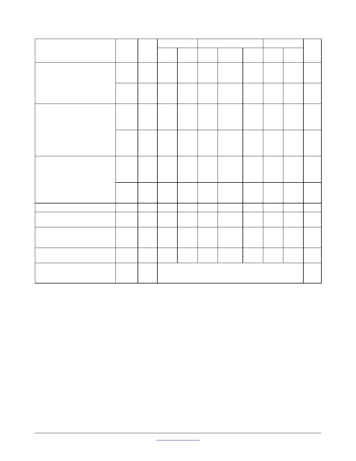
ELECTRICAL CHARACTERISTICS (Voltages Referenced to V
SS
)
Characteristic Symbol
V
DD
Vdc
− 55_C 25_C 125_C
Unit
Min Max Min Typ
(Note 2)
Max Min Max
Output Voltage “0” Level
V
in
= V
DD
or 0
V
OL
5.0
10
15
−
−
−
0.05
0.05
0.05
−
−
−
0
0
0
0.05
0.05
0.05
−
−
−
0.05
0.05
0.05
Vdc
“1” Level
V
in
= 0 or V
DD
V
OH
5.0
10
15
4.95
9.95
14.95
−
−
−
4.95
9.95
14.95
5.0
10
15
−
−
−
4.95
9.95
14.95
−
−
−
Vdc
Input Voltage “0” Level
(V
O
= 4.5 or 0.5 Vdc)
(V
O
= 9.0 or 1.0 Vdc)
(V
O
= 13.5 or 1.5 Vdc)
V
IL
5.0
10
15
−
−
−
1.5
3.0
4.0
−
−
−
2.25
4.50
6.75
1.5
3.0
4.0
−
−
−
1.5
3.0
4.0
Vdc
“1” Level
(V
O
= 0.5 or 4.5 Vdc)
(V
O
= 1.0 or 9.0 Vdc)
(V
O
= 1.5 or 13.5 Vdc)
V
IH
5.0
10
15
3.5
7.0
11
−
−
−
3.5
7.0
11
2.75
5.50
8.25
−
−
−
3.5
7.0
11
−
−
−
Vdc
Output Drive Current
(V
OH
= 2.5 Vdc) Source
(V
OH
= 9.5 Vdc)
(V
OH
= 13.5 Vdc)
I
OH
5.0
10
15
–4.19
–7.96
–16.3
−
−
−
–3.38
–6.42
–13.2
–6.75
–12.83
–26.33
−
−
−
–2.37
–4.49
−9.24
−
−
−
mAdc
(V
OL
= 0.4 Vdc) Sink
(V
OL
= 0.5 Vdc)
(V
OL
= 1.5 Vdc)
I
OL
5.0
10
15
1.93
4.96
19.3
−
−
−
1.56
4.0
15.6
3.12
8.0
31.2
−
−
−
1.09
2.8
10.9
−
−
−
mAdc
Input Current I
in
15 − ±0.1 − ±0.00001 ±0.1 − ±1.0 mAdc
Input Capacitance
(V
in
= 0)
C
in
− − − − 5.0 7.5 − − pF
Quiescent Current
(Pin 5 is High)
Auto Reset Disabled
I
DD
5.0
10
15
−
−
−
5.0
10
20
−
−
−
0.005
0.010
0.015
5.0
10
20
−
−
−
150
300
600
mAdc
Auto Reset Quiescent Current
(Pin 5 is low)
I
DDR
10
15
−
−
250
500
−
−
30
82
250
500
−
−
1500
2000
mAdc
Supply Current (Notes 3 & 4)
(Dynamic plus Quiescent)
I
D
5.0
10
15
I
D
= (0.4 mA/kHz) f + I
DD
I
D
= (0.8 mA/kHz) f + I
DD
I
D
= (1.2 mA/kHz) f + I
DD
mAdc
Product parametric performance is indicated in the Electrical Characteristics for the listed test conditions, unless otherwise noted. Product
performance may not be indicated by the Electrical Characteristics if operated under different conditions.
2. Data labelled “Typ” is not to be used for design purposes but is intended as an indication of the IC’s potential performance.
3. The formulas given are for the typical characteristics only at 25_C.
4. When using the on chip oscillator the total supply current (in mAdc) becomes: I
T
= I
D
+ 2 C
tc
V
DD
f x 10
–3
where I
D
is in mA, C
tc
is in pF,
V
DD
in Volts DC, and f in kHz. (see Fig. 3) Dissipation during power−on with automatic reset enabled is typically 50 mA @ V
DD
= 10 Vdc.
 Loading...