WIRING CONNECTIONS
Most local regulations require that wiring connec-
tions be made by a licensed electrician and that the
installation be inspected and approved before opera-
tion.
All connections, wire sizes, etc. must conform to
requirements of electrical codes in effect at the
installation site.
Generator set grounding must be in accordance with
National Electrical Code (NFPA 70-1975) Article 250.
If the installation is for standby service, a double
throw transfer switch must always be used. Connect
this switch (either automatic or manual) so that it is
impossible for commercial power and generator
current to be connected to the load at the same time.
See Figure 17. Instructions for connecting an
automatic load transfer control are included with
such equipment.
LINE LOAD
GEN.
NOTE:
SHOWN WITH LINE CONNECTED TO LOAD.
FIGURE 17. LOAD TRANSFER SWITCH
(TYPICAL FUNCTION)
Control Box Connections: The factory ships these 12
lead generators with load connection wires NOT
connected together in the control box. These.12 wires
are labeled Tl through T12 and must be brought
together before making load connections. Proceed as.
follows: - -
1.
Remove either right, left or top panel from control
box. See Figure 18..
2.
Connect wires together as shown on panel draw-
ing and in Figure 1 according to voltage desired.
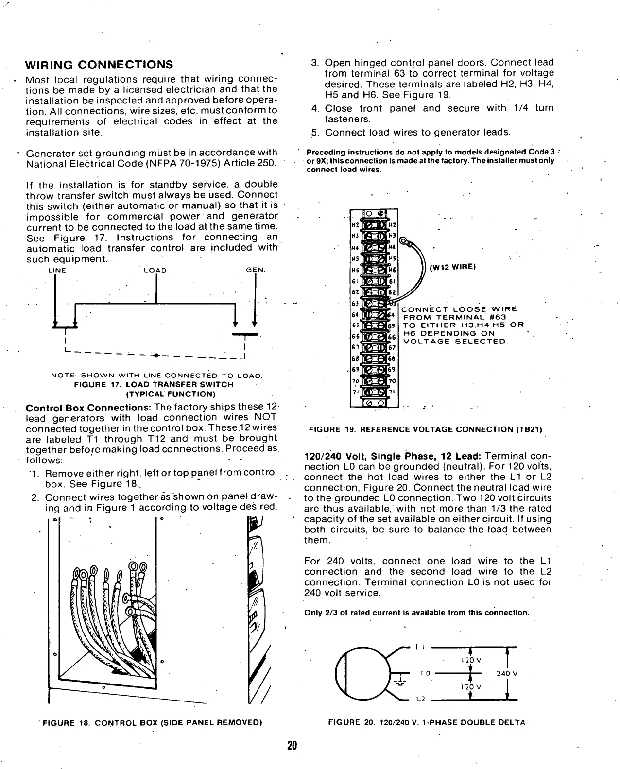
3. Open hinged control panel doors. Connect lead
from terminal 63 to correct terminal for voltage
desired.
These terminals are labeled H2, H3, H4,
H5 and H6. See Figure 19.
4.
Close front panel and secure with 1/4 turn
fasteners.
5. Connect load wires to generator leads.
Preceding instructions do not apply to models designated Code 3
or 9X; this connection is made at the factory. The installer must only
connect load wires.
(W12 WIRE)
CONNECT LOOSE WIRE
FROM TERMINAL #63
TO EITHER H3.H4.H5 OR
H6 DEPENDING ON
VOLTAGE SELECTED.
FIGURE 19. REFERENCE VOLTAGE CONNECTION (TB21)
120/240 Volt, Single Phase, 12 Lead: Terminal
con-
nection LO can be grounded (neutral). For 120 volts,
connect the hot load wires to either the Ll or L2
connection, Figure 20. Connect the neutral load wire
to the grounded L0 connection. Two 120 volt circuits
are thus available, with not more than 1/3 the rated
capacity of the set available on either circuit. If using
bpth circuits, be sure to balance the load between
them.
For 240 volts, connect one load wire to the Ll
connection and the second load wire to the L2
connection. Terminal connection L0 is not used for
240 volt service.
Only 2/3 ot rated current is available from this connection.
FIGURE 18. CONTROL BOX (SIDE PANEL REMOVED)
FIGURE 20. 120/240 V.
1-PHASE
DOUBLE DELTA
20
 Loading...
