Priming Fuel System: Verify that
all
connections
in
the fuel system are secure and no leaks exist. Proceed
with priming
as
follows:
1.
.Open bleed screw
on the
inlet side
of
fuel filter.
See Figure
24.
2.
Actuate priming lever
on the
side
of the
fuel
transfer pump (Figure
13)
until fuel flows from
filter bleed screw without showing
air
bubbles.
3. Close filter inlet bleed screw.
"
4.
Open bleed screw
on
the outlet side
of
filter. See
Figure
24.
5. Again, actuate priming lever until
a
bubble-free
flow
of
fuel comes
out of the
bleed screw.
6. Close filter outlet bleed screw.
7. Open
one or two
bleed screws
on
fuel injection
pump.
8. Repeat priming lever actuation until bubble-free
fuel
is
emitted from bleed screws
on
injection
pump.
9. Close bleed screw(s).
10.
Torque
all the
bleed screws.
Filter—5-7 Ib-ft (6.88
to 9.5 N.m)
Pump—3-5 Ib-ft (4.1
to 6.8 N.m)
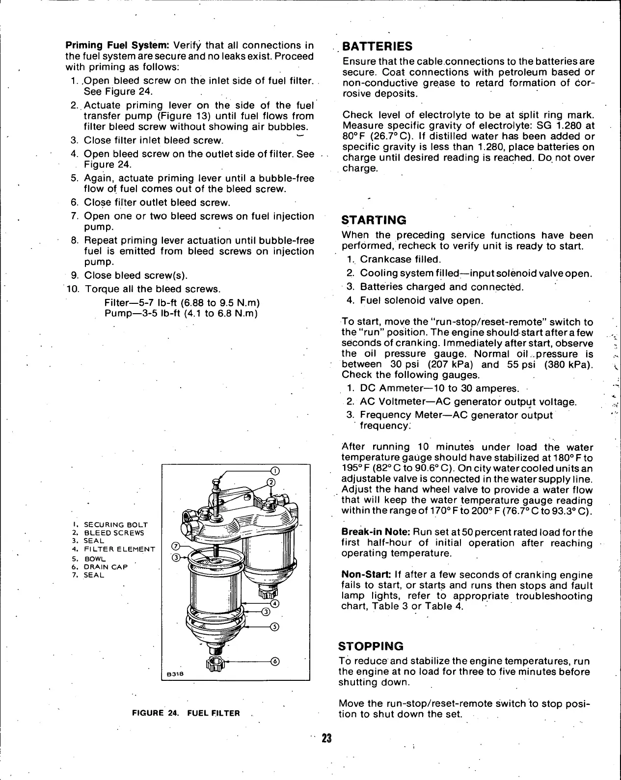
1.
SECURING BOLT
2.
BLEED SCREWS
3. SEAL
4.
FILTER ELEMENT
5. BOWL
6. DRAIN
CAP
7. SEAL
FIGURE 24. FUEL FILTER
BATTERIES
Ensure that the cable.connections
to
the batteries are
secure. Coat connections with petroleum based
or
non-conductive grease
to
retard formation
of
cor-
rosive deposits.
Check level
of
electrolyte
to be at
split ring mark.
Measure specific gravity
of
electrolyte:
SG 1.280 at
80°F (26.7°C).
If
distilled water
has
been added
or
specific gravity
is
less than
1.280,
place batteries
on
charge until desired reading
is
reached. Do,
not
over
charge.
STARTING
When
the
preceding service functions have been
performed,
recheck
to
verify unit
is
ready
to
start.
1.
Crankcase filled.
2.
Cooling system filled—input solenoid valve open.
3. Batteries charged
and
connected.
4.
Fuel solenoid valve open.
To start, move the "run-stop/reset-remote" switch
to
the "run" position. The engine should start after a few
seconds
of
cranking. Immediately after start, observe
the
oil
pressure gauge. Normal
oil
.pressure
is
between
30 psi
(207 kPa)
and 55 psi
(380 kPa).
Check
the
following gauges.
1.
DC
Ammeter—10
to 30
amperes.
2.
AC
Voltmeter—AC generator output voltage.
3. Frequency Meter—AC generator output
frequency.
After running
10
minutes under load
the
water
temperature gauge should have stabilized
at
180° Fto
195°
F
(82° C
to
90.6° C). On city watercooled units an
adjustable valve
is
connected in the water supply line.
Adjust
the
hand wheel valve
to
provide
a
water flow
that will keep
the
water temperature gauge reading
within the range
of
170°
F
to 200° F (76.7° C to 93.3° C).
Break-in Note: Run set at 50 percent rated load forthe
first half-hour
of
initial operation after reaching
operating temperature.
Non-Start:
If
after
a few
seconds
of
cranking engine
fails
to
start,
or
starts
and
runs then stops and fault
lamp lights, refer
to
appropriate troubleshooting
chart, Table
3 or
Table
4.
STOPPING
To reduce and stabilize the engine temperatures,
run
the engine
at no
load
for
three
to
five minutes before
shutting down.
Move
the
run-stop/reset-remote switch
to
stop
posi-
tion
to
shut down
the set.
23
 Loading...
