6-6
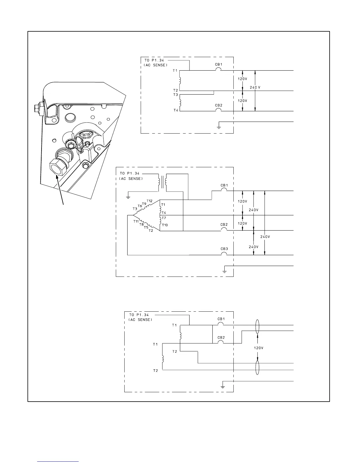
1/2 INCH CONDUIT
CONNECTOR FOR AC
LEADS—BOTTOM,
LEFT END OF BASE
3-PHASE — 110/120V, 115/230V, 120/240V
1
“2-WIRE” — 100-120V
1,
2
STANDARD 3-WIRE— 100/200V, 115/230V, 120/240V
1
GENSET
GENSET
GENSET
WH
T
GRN
BLK
WH
T
GRN
BLK
WH
T
GRN
BLK/
YLW
BLK
BLK
GN
D
GN
D
G
ND
WH
T
BLK
CB2–LOA
D (L1)
CB2–LOA
D (L2)
CB3–LOA
D (L3)
NEUTRAL
(L0)
NEUTRAL
(L0)
CB1–LOA
D (L1)
NEUTRAL
(L0)
CB1–LOA
D (L1)
CB1–LOA
D (L1)
NEUTRAL
(L0)
CB2–LOA
D (L2)
1. These are not reconnectable
generators.
2. Because the two generator
windings marked T1-T2 are in
phase, the “neutral” conductors
in the connected equipment,
such as between a transfer
switch and main distribution
panel, must be sized to carry the
sum of the currents.
BLK/
YLW
FIGURE 6-3. CONNECTION DIAGRAMS AND AC LEAD OUTLET
 Loading...


