8-1
8. Fuel System
GASOLINE FUEL SYSTEM—HGJAA &
HGJAD
See the Operator’s Manual for recommended fuels
and Section 13. Specifications for fuel consumption
rates.
WARNING
Gasoline is flammable and explo-
sive and can cause severe personal injury or
death — Do not smoke — Keep flames, sparks,
pilot lights, switches, arc-producing equipment
and all other ignition sources away from fuel,
fuel components and areas sharing ventilation
— Keep an ABC fire extinguisher handy.
CAUTION
Unauthorized modifications or re-
placement of fuel, exhaust, air intake or speed
control system components that affect engine
emissions are prohibited by law in the State of
California.
Operation
These genset models are equipped with sequential,
multi-port fuel injection (Figure 8-1). A remote high-
pressure fuel pump (Figure 8-8) supplies fuel to the
genset. The fuel rail pressure regulator maintains a
constant fuel pressure differential across the injec-
tors (43.5 psi [300 kPa] nominal). The genset con-
troller (Section 5, Control):
1. Monitors and governs AC output frequency
(Table 8-1) as load varies by means of the
throttle, which regulates the mass of air induc-
ted each engine cycle.
2. Monitors absolute intake manifold air pressure
(MAP) to determine engine load and modify the
calculations of inducted air mass.
3. Monitors absolute intake manifold air tempera-
ture (MAT) to modify the calculations of induc-
ted air mass.
4. Monitors the ignition pulses to determine fuel
injector timing.
5. Energizes the fuel injectors. Injector fuel deliv-
ery is proportional to pulse width, which the
controller calculates on the basis of MAP and
MAT to provide the desired air fuel ratio (AFR).
6. Enriches AFR during cranking, warm-up and
heavy load transients for good starting and per-
formance.
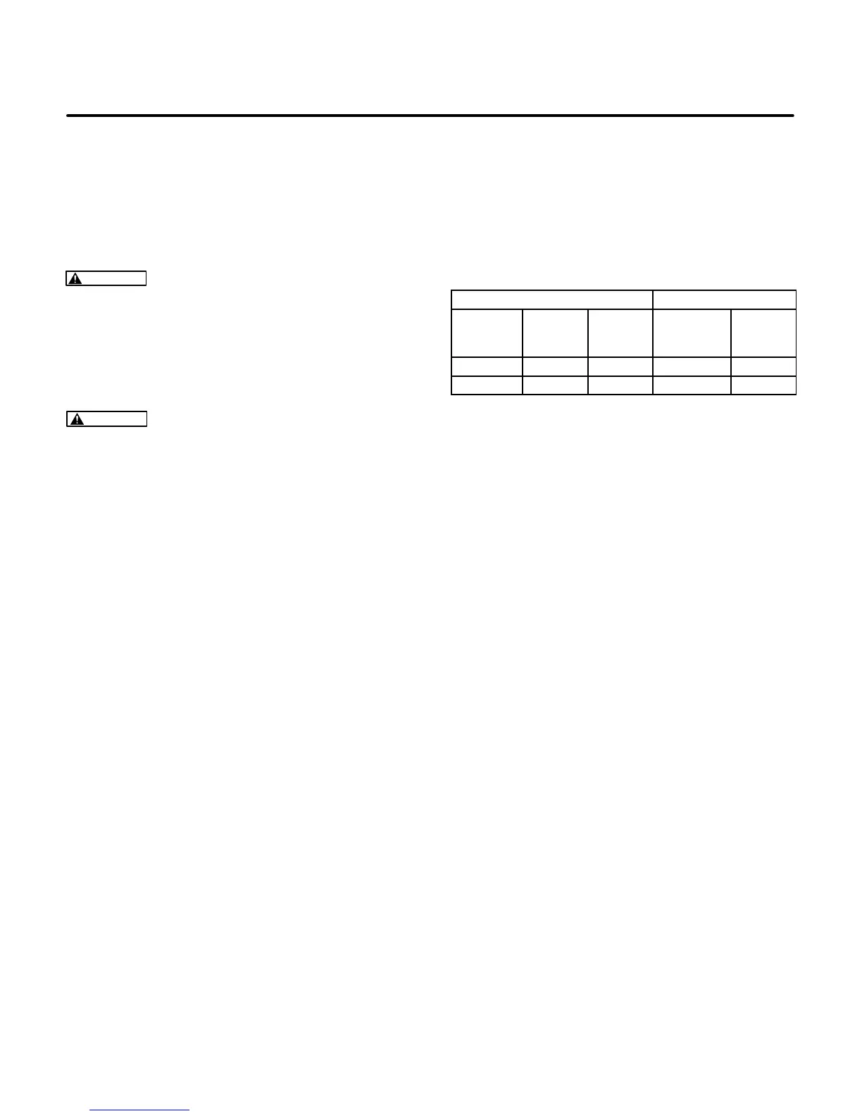
TABLE 8-1 VOLTAGE / FREQUENCY / DROOP
Voltage Frequency (Hz)
Rated
Voltage
(60 Hz)
Max
No Load
Min Full
Load
No Load Droop
120 125 115 60.5/59.5 N/A
240 250 230 60.5/59.5 N/A
Removing Throttle Body
The throttle body can be removed without removing
the genset enclosure. Referring to Figure 8-1, re-
move the throttle body as follows:
1. Disconnect the fuel supply hose at the outlet of
the fuel filter and the return fuel hose at the out-
let to the fuel pressure regulator.
2. Disconnect the leads to the throttle body, MAP
and MAT sensors and fuel injectors.
3. Remove the air filter cover and filter element
and remove the two support screws in the back
of the filter enclosure as well as the two throttle
body mounting nuts.
4. Pull away the air filter enclosure and throttle
body.
5. Avoid removing the throttle body through studs
from the intake manifold. Otherwise, they will
have to be replace with new studs having facto-
ry-applied thread sealant.
Removing Intake Manifold
Remove the genset enclosure and perform Steps1
through 3 of Removing Throttle Body. (Do not loos-
en the throttle body mounting nuts if the air filter,
throttle body and manifold are to be removed as an
assembly.) Then remove the intake manifold bolts
and pull away the assembly.
 Loading...


