7-1
7. Fan, Drive Belt, Flywheel, Ignition, Exhaust
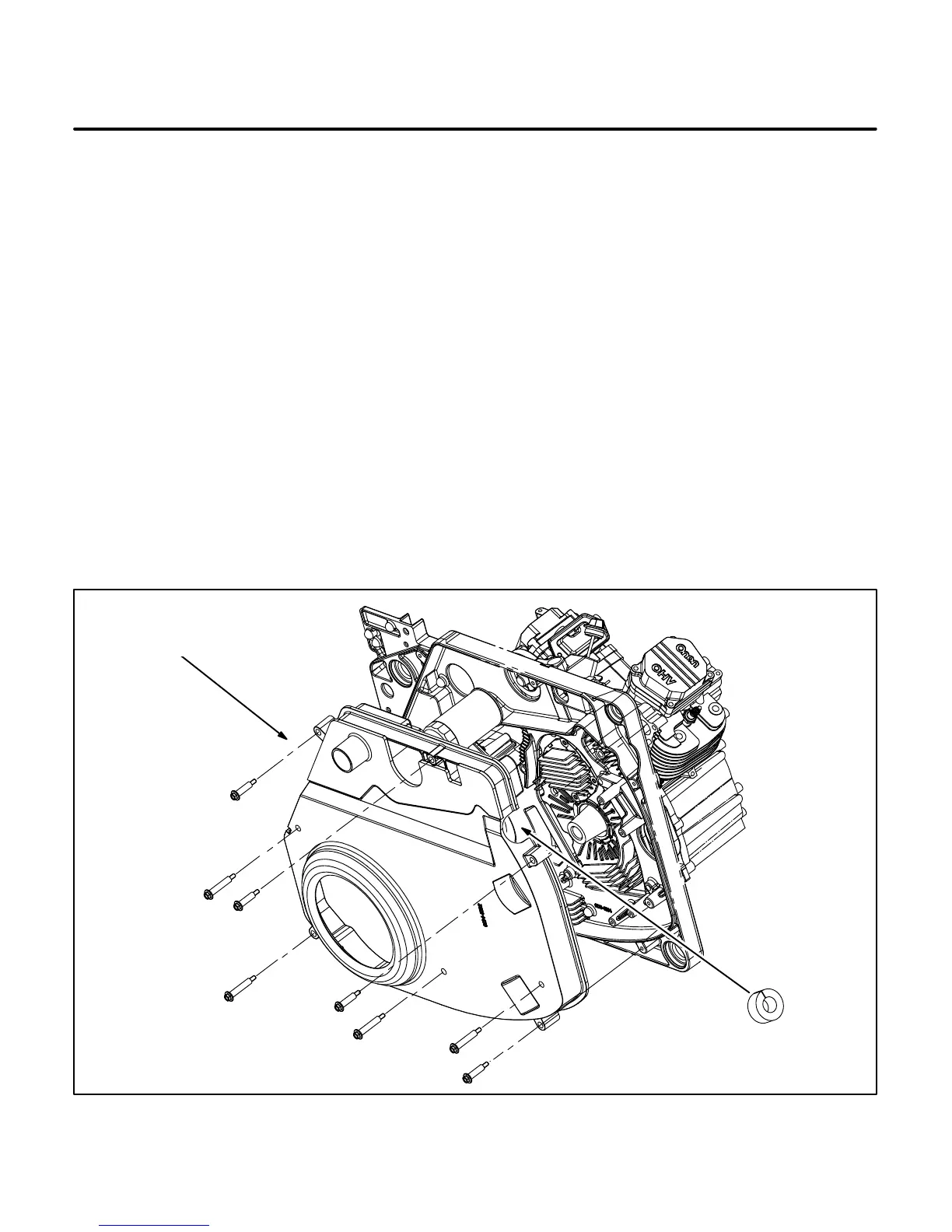
The fan shroud (Figure 7-1) on the underside of the
generator/engine assembly encloses the cooling
fan, belt drive, flywheel, ignition coils (magnetos)
and exhaust manifold.
FAN, BELT, PULLEYS AND FLYWHEEL
The engine drives the generator by means of a 4-rib
“Poly-Vee” belt (Figure 7-2). The engine pulley is
coupled to the engine side of the flywheel, which is
center-bolted and keyed to the engine crankshaft
taper. The cooling fan and backplate are bolted di-
rectly to the generator pulley, which is center-bolted
to the generator rotor shaft taper. The various gen-
erator/engine speed combinations tabulated in
Section 13. Specifications are obtained by employ-
ing various pulley ratios.
The generator pulley must be removed to remove
the generator rotor shaft and the flywheel assembly
to remove the engine.
Removing Fan and Generator Pulley
1. Remove the generator/engine assembly from
the genset. See REMOVING / INSTALLING
GENERATOR / ENGINE ASSEMBLY, Sec-
tion 9. Engine.
2. Remove the eight fan shroud bolts and remove
the fan shroud (Figure 7-1).
3. Remove the three bolts securing the fan (blow-
er) and its back plate (Figure 7-2) and remove
them from the pulley.
4. Block the generator pulley and remove the cen-
ter bolt. Use a wheel puller to break the pulley
free of the generator shaft taper. Three M6 bolt
tappings are provided on the face for pulling.
5. Turn the belt tensioner away from the belt with
a 1/2 inch socket driver and block it there while
lifting off the generator pulley.
FAN
SHROUD
EXHAUST
MANIFOLD
INSULATION
*
*
*
*
* – SHORT BOLTS
FIGURE 7-1. FAN SHROUD
 Loading...


