7-5
Ignition Coils (Magnetos)
Ignition Coil Resistance Test: If spark is weak or
inconsistent across either spark plug, check ignition
coil resistance between a good ground on the en-
gine and each spark plug cable terminal. Replace
an ignition coil assembly if its electrical resistance
exceeds the maximum specified in Table 7-1.
TABLE 7-1. IGNITION COIL RESISTANCES
MINIMUM* MAXIMUM*
LEFT (No. 1 Cyl) 13,700 Ohms 33,000 Ohms
RIGHT (No. 2 Cyl) 11,500 Ohms 27,000 Ohms
* – Meter polarity is critical. Connect positive (+) lead to
ground.
Removal: If spark is weak or inconsistent across ei-
ther spark plug and/or coil resistance is high or low,
remove the ignition coil assembly as follows:
1. Remove the generator/engine assembly from
the genset. See REMOVING / INSTALLING
GENERATOR / ENGINE ASSEMBLY, Sec-
tion 9. Engine.
2. Remove the eight fan shroud bolts and remove
the fan shroud (Figure 7-1).
3. Disconnect the ignition kill lead at the coil termi-
nal, pull the spark plug cable through the grom-
met in the base and remove the two ignition coil
mounting screws.
Installation: is the reverse of assembly. Set the air
gaps. Note in Figure 7-3 the location of the coil as-
sembly that has the longer spark plug cable, which
goes to cylinder No. 1 (left, or generator side of en-
gine).
Setting Air Gaps: To set the air gaps bar the engine
until the lands on the flywheel directly face the coils.
Place a 0.012 inch (0.03 mm) thick feeler gauge be-
tween the coil and the land on the flywheel, hold the
coil tight up against the feeler gauge and land and
torque the two mounting bolts to 5 lb-ft (7 N-m).
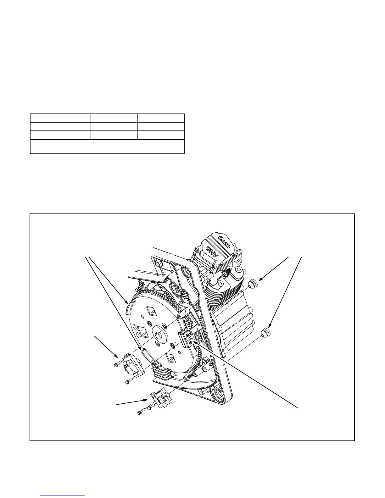
GROMMETS—FOR
SPARK PLUG CABLES
AND IGNITION KILL LEADS
IGNITION COIL
(LONGER CABLE) FOR
CYLINDER #1 (LEFT)
IGNITION COIL
(SHORTER CABLE)
FOR CYLINDER #2
(RIGHT)
FLYWHEEL
MAGNET
FLYWHEEL LANDS— BAR
ENGINE UNTIL LANDS FACE
COILS AND SET AIR GAPS
FIGURE 7-3. IGNITION COILS (MAGNETOS)
 Loading...


