8-10
Carburetor
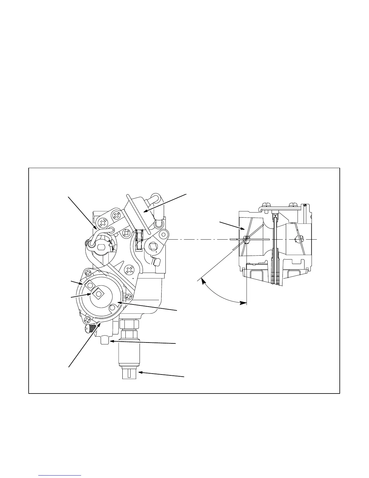
The carburetor (Figure 8-10) is not likely to cause
problems and should be replaced only after all other
problems have been eliminated (see Section 11.
Troubleshooting). The carburetor fuel mixture ad-
justments are sealed at the factory. See Page 8-20
to connect the throttle link and to adjust the idle
(throttle) stop screw.
Automatic Choke
The automatic choke is operated by a bi-metal/heat-
er assembly and a vacuum breaker assembly (Fig-
ure 8-10). Conduct the following checks and adjust-
ments before replacing a carburetor/choke
assembly:
1. Apply 12 VDC across the heater terminals. The
choke should open fully in 2 to 3 minutes.
2. Check the heater alignment marks and realign
if out of alignment. The choke should be closed
at temperatures below 70° F (21° C). It may be
partly open above 70° F (21° C), but should
close almost completely when vibrated (engine
cranked).
3. The vacuum breaker diaphragm must not leak
under a vacuum of 30 inches Hg (100 kPa). It
should not take a vacuum greater than
2.4 inches Hg (8 kPa) to open the choke fully.
At a vacuum of 1 inch Hg (3.2 kPa) the choke
plate should be at the angle shown (Fig-
ure 8-10). If necessary, bend the link at the
point shown, using two pliers.
47°–53° @
–3.2 kPa & 25° C
FUEL CUTOFF
SOLENOID E4
CHOKE BI-METAL/
HEATER ASSEMBLY
HEATER
ALIGNMENT
MARKS
B+
B–
CHOKE
PLATE
VACUUM BREAKER
ASSEMBLY
FLOAT BOWL
DRAIN
BREAKER
LINK
FIGURE 8-10. CARBURETOR / CHOKE ASSEMBLY
 Loading...


