9-9
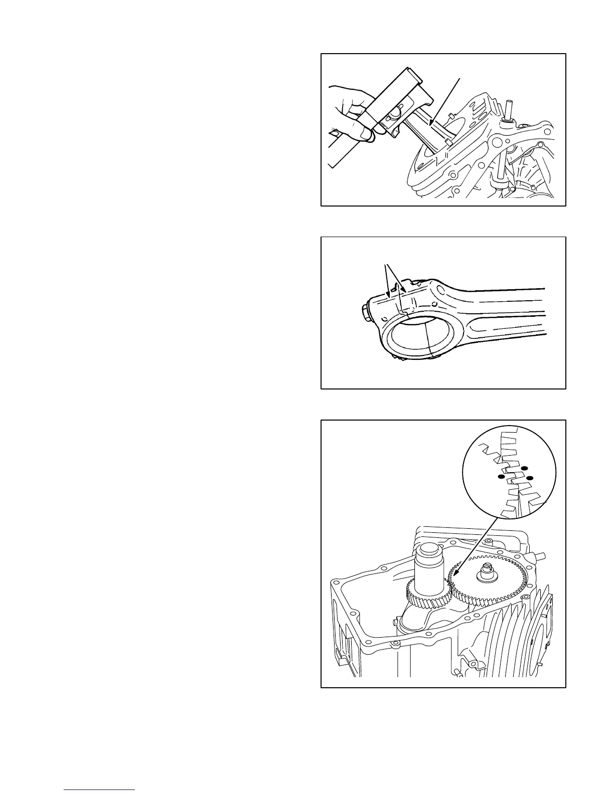
Piston / Connecting Rod Assembly
Assemble the pistons and connecting rods using
both circlips to hold the piston pin in the piston. Note
that one connecting rod is marked “1” and the other
“2” (Figure 9-9). Assemble in the respective cylinder
with the markings on the main bearing cover side.
When installing the connecting rod caps, make sure
the alignment marks register (Figure 9-10). Torque
the cap bolts to 16.3-19.9 lb-ft (22.1-27 N-m).
Check for free movement of piston and connecting
rod by turning the crankshaft slowly.
Camshaft and Tappets
Reinstall the tappets in their original bores. Push
them in fully to avoid damage during camshaft
installation. Install the camshaft and line up the tim-
ing marks with the crankshaft gear (Figure 9-11).
1
NO. 1 MARK
FIGURE 9-9. INSTALLING PISTON / ROD
ALIGNMENT MARKS
FIGURE 9-10. ROD ALIGNMENT MARKS
FIGURE 9-11. TIMING MARKS
 Loading...


