Thoroughly clean the valve seat counterbore and
remove any burrs from the edges. If the counterbore
is damaged, machine for an oversize seat. Oversize
seats are available in .002”,
.005”,
-010“ and .025”.
Otherwise, install new standard-size seat inserts.
Drive the new valve seat inserts into place. Each seat
must rest solidly on the bottom of the counterbore at
all points. To ease installation, heat the cylinder head
in an oven at 325°F for about 1/2 hour and cool the
valve seats in dry ice.
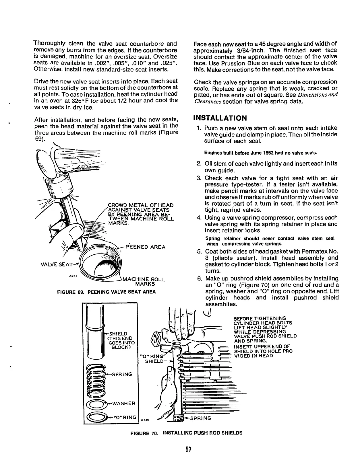
After installation, and before facing the new seats,
peen the head material against the valve seat in the
three areas between the machine roll marks (Figure
69).
CROWD METAL
OF
HEAD
AGAl
NST
VALVE SEATS
BY
PEEN
I
NG AREA
BE-
VALV
€
SEAT
FIGURE
69.
PEENING VALVE SEAT AREA
SPR
I
NG
-WASHER
Face each new seat to a 45 degree angle and width of
approximately 3/64-inch. The finished seat face
should contact the approximate center of the valve
face. Use Prussion Blue on each valve face to check
this. Make corrections to the seat, not the valve face.
Check the valve springs on an accurate compression
scale. Replace any spring that is weak, cracked or
pitted, or has ends out of square. See
Dimensions and
Clearances
section for valve spring data.
INSTALLATION
1.
Push a new valve stem oil seal onto each intake
valve guide and clamp in place. Then oil the inside
surface of each seal.
Engines
built
before June
1962
had no valve seals.
2. Oil stem of each valve lightly and insert each in its
own guide.
3.
Check each valve for a tight seat with an air
pressure type-tester. If a tester isn’t available,
make pencil marks at intervals on the valve face
and observe if marks rub off uniformly when valve
is rotated part of a turn
in
seat. If the seat isn’t
tight, regrind valves.
4.
Using a valve spring compressor, compress each
valve spring with its spring retainer in place and
insert retainer locks.
Spring retainer should never contact valve stem seal
wnen compressing valve springs.
5.
Coat both sides of head gasket with Permatex
No.
3
(pliable sealer). Install head assembly and
gasket to cylinder block. Tighten head bolts 1 or2
turns.
6. Make up pushrod shield assemblies by installing
an
“0”
ring (Figure 70) on one end of rod and a
spring, washer and
“0”
ring on opposite end. Lift
cylinder heads and install pushrod shield
assemblies.
‘I
11
A145
BEFORE TlGHTE
N
I
NG
CYLINDER HEAD BOLTS
LIFT HEAD SLIGHTLY
WHILE DEPRESSING
VALVE PUSH ROD SHIELD
AND SPRING.
INSERT UPPER END
OF
SHIELD INTO HOLE
PRO-
VIDED
IN
HEAD.
FIGURE
70.
INSTALLING PUSH ROD SHIELDS
57
Redistribution or publication of this document,
by any means, is strictly prohibited.
 Loading...


