7.
8.
9.
10.
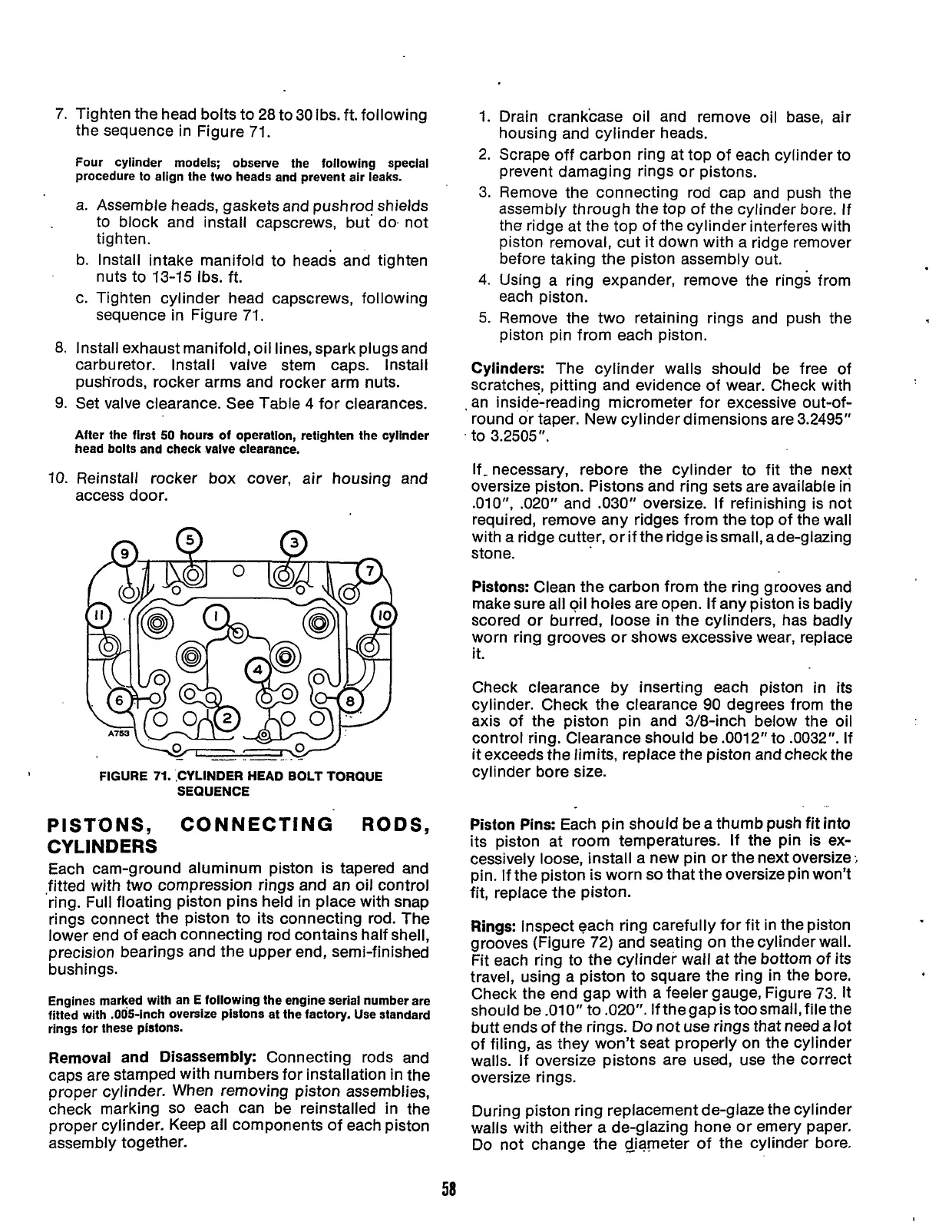
Tighten the head bolts to 28 to 30 Ibs. ft. following
the sequence in Figure 71.
Four cyiinder models; observe the following special
procedure to align the two heads and prevent air leaks.
a.
b.
C.
Assemble heads, gaskets and pushrod shields
to block and install capscrews, but do. not
tighten.
Install intake manifold to heads and tighten
nuts to 13-15 Ibs. ft.
Tighten cylinder head capscrews, following
sequence in Figure
71.
Install exhaust manifold, oil lines, spark plugs and
carburetor. Install valve stem caps. Install
push'rods, rocker arms and rocker arm nuts.
Set valve clearance. See Table 4 for clearances.
After the first
50
hours
of
operation, retighten the cylinder
head bolts and check valve clearance.
Reinstall rocker box cover, air housing and
access door.
-
..
.. . .-
FIGURE
71.
,CYLINDER HEAD BOLT TORQUE
SEQUENCE
PISTONS, CONNECTING
RODS,
CYLINDERS
Each cam-ground aluminum piston is tapered and
fitted with two compression rings and an oil control
'ring. Full floating piston pins held in place with snap
rings connect the piston to its connecting rod. The
lower end of each connecting rod contains half shell,
precision bearings and the upper end, semi-finished
bushings.
Engines marked with an E following the engine serial number are
fitted with .OO!ji-inch Oversize pistons at the factory. Use standard
rings for these pistons.
Removal and Disassembly:
Connecting rods and
caps are stamped with numbers for installation in the
proper cylinder. When removing piston assemblies,
check marking
so
each can be reinstalled in the
proper cylinder. Keep all components of each piston
assembly together.
1.
2.
3.
4.
5.
Drain crankcase oil and remove oil base, air
housing and cylinder heads.
Scrape off carbon ring at top of each cylinder to
prevent damaging rings or pistons.
Remove the connecting rod cap and push the
assembly through the top of the cylinder bore.
If
the ridge at the top of the cylinder interferes with
piston removal, cut it down with a ridge remover
before taking the piston assembly out.
Using a ring expander, remove the rings from
each piston.
Remove the two retaining rings and push the
piston pin from each piston.
Cylinders:
The cylinder walls should be free of
scratches, pitting and evidence of wear. Check with
.
an inside-reading micrometer for excessive out-of-
round or taper. New cylinder dimensions are 3.2495"
.
to 3.2505".
If-necessary, rebore the cylinder to fit the next
oversize piston. Pistons and ring sets are available in
.010",
.020" and .030" oversize.
If
refinishing is not
required, remove any ridges from the top of the wall
with
a
ridge cutter, or if the ridge is small, ade-glazing
stone.
Pistons:
Clean the carbon from the ring grooves and
make sure all oil holes are open. If any piston
is
badly
scored or burred, loose in the cylinders, has badly
worn ring grooves or shows excessive wear, replace
it.
Check clearance by inserting each piston in its
cylinder. Check the clearance
90
degrees from the
axis of the piston pin and 3/8-inch below the oil
control ring. Clearance should be .0012" to .0032".
If
it exceeds the limits, replace the piston and check the
cylinder bore size.
..
Piston Pins:
Each
pin
should be a thumb push fit into
its piston at room temperatures. If the pin
is
ex-
cessively loose, install a new
pin
or the next oversize
;
pin.
If
the piston is worn
so
that the oversize pin won't
fit, replace the piston.
Rings:
Inspect each ring carefully for fit in the piston
grooves (Figure 72) and seating on the cylinder wall.
Fit each ring to the cylinder wall at the bottom of its
travel, using a piston to square the ring in the bore.
Check the end gap with a feeler gauge, Figure 73. It
should be
.010"
to .020". If thegap is toosmall,file the
butt ends of the rings.
Do
not use rings that need
a
lot
of filing, as they won't seat properly on the cylinder
walls.
If
oversize pistons are used, use the correct
oversize rings.
During piston ring replacement de-glaze the cylinder
walls with either a de-glazing hone or emery paper.
Do not change the Giameter of the cylinder bore.
58
Redistribution or publication of this document,
by any means, is strictly prohibited.
 Loading...


