17
+
-
+
-
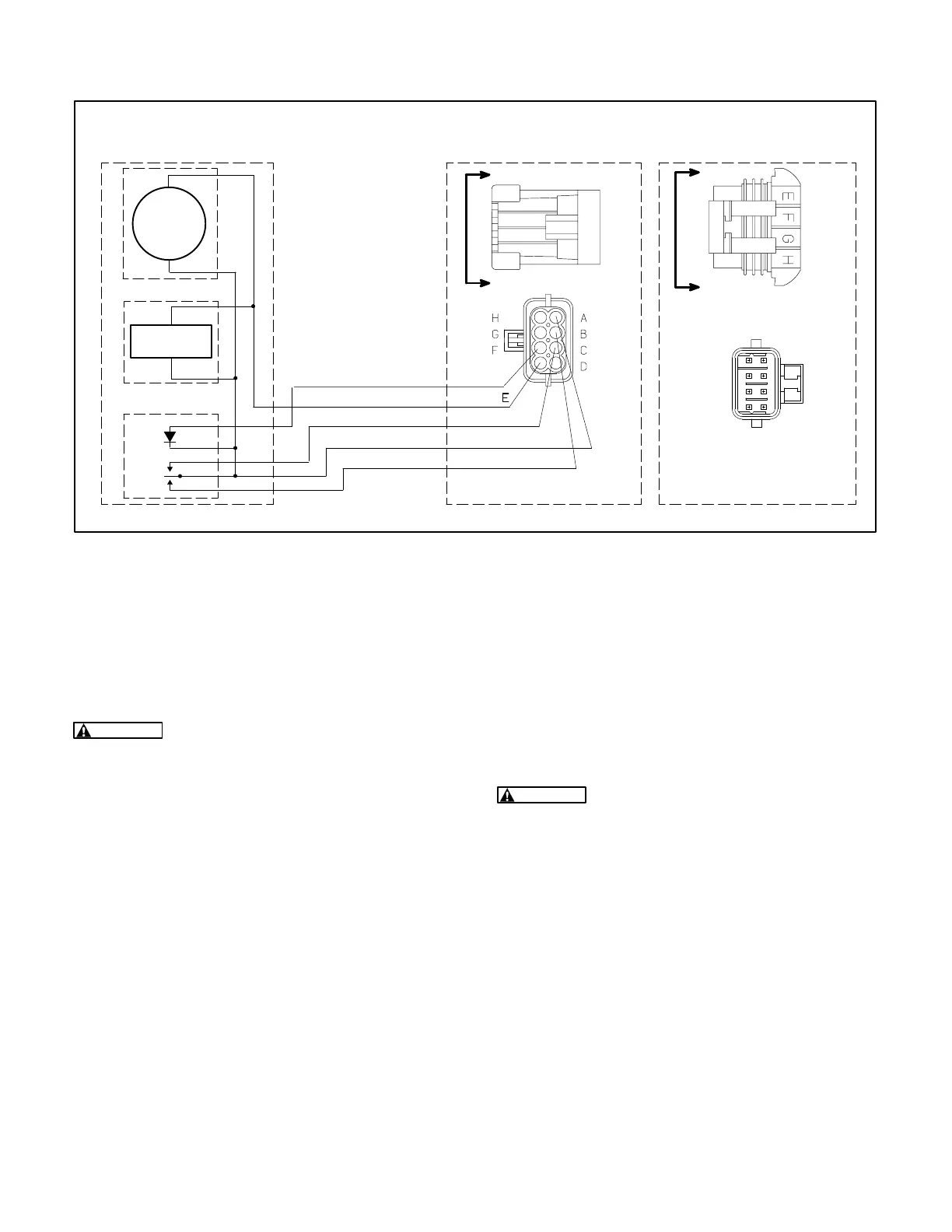
REMOTE CONTROL
CONNECTOR
REMOTE CONTROL
PANEL
START
GND
REMOTE RUN
STOP
START/STOP SWITCH
DC VOLTMETER
DC
VOLTMETER
+
-
HOUR METER
HOUR METER
OPTIONAL
OPTIONAL
A
B
C
F
GENSET
CONNECTOR
E
F
GH
WIRE END
CONNECTOR END
WIRE END
CONNECTOR END
A
B
C
D
E
F
G
H
A
A
B
B
WIRE END
(VIEW B-B)
CONNECTOR END
(VIEW A-A)
LED
STATUS
INDICATOR LIGHT
FIGURE 19. SCHEMATIC OF TYPICAL REMOTE CONTROL CONNECTIONS
BATTERY CONNECTIONS
Do not connect the battery cables to the battery until
Installation Review and Startup
(Page 20) to pre-
vent accidental starting of the genset during installa-
tion.
WARNING
Accidental starting of the genset
can cause severe personal injury or death. Do
not connect the starting battery until Installa-
tion Review and Startup (Page 20).
The genset has a 12 VDC, negative-ground engine
control and cranking system. See
Specifications
for
the requirements for cranking batteries.
Battery Compartment
Batteries must be mounted in a separate compart-
ment from that of the genset and away from spark-
producing equipment. A compartment must have
openings of at least 1.7 square inches (11 square
centimetres) at the top and bottom for ventilation of
battery gasses. It should be mounted such that
spills and leaks will not drip acid on fuel lines, wiring
and other equipment that could be damaged.
WARNING
Arcing can ignite the explosive hy-
drogen gas given off by the battery, causing se-
vere personal injury. The battery compartment
must be ventilated and must isolate the battery
from spark-producing equipment.
Redistribution or publication of this document,
by any means, is strictly prohibited.
 Loading...


