9-5
OPTIONAL REMOTE DIGITAL DISPLAY
WARNING
Accidental or remote starting can
cause severe personal injury or death. Before
removing a panel or access door, disconnect
the negative (–) cable at the battery to prevent
the engine from starting.
See DIGITAL DISPLAY (p. 2-2) regarding function.
See Page A-1 for connections.
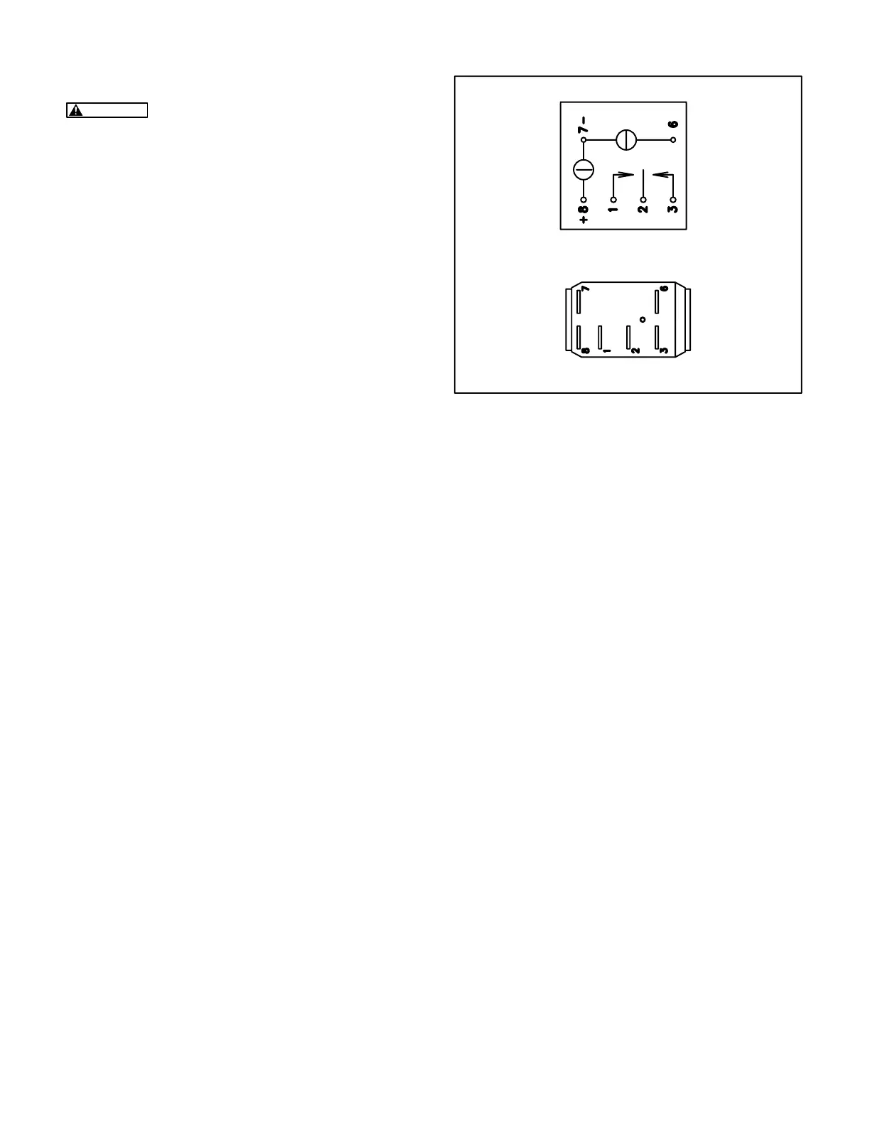
LOCAL/REMOTE CONTROL SWITCH (S4)
The control switch, when located on the genset, is
mounted on the control panel (Figure 9-1). Unsnap
the connector for access to its terminals (Fig-
ure 9-3). Replace the switch if Start does not close
terminals 2 and 3, Stop does not close terminals 1
and 2, Green does not light when battery voltage is
applied across terminals 7 (–) and 8 (+), or Amber
when battery voltage is applied to terminals 7 (–)
and 6 (+).
EMERGENCY STOP SWITCH (CB1)
The switch/circuit breaker is mounted on the control
panel (Figure 9-1). Disconnect the leads and check
electrical continuity across the two terminals. Re-
place the circuit breaker if it does not reset or turn
ON and OFF. For easier access to the switch termi-
nals, push out the four plastic buttons that secure
the panel and pull the panel and switch forward.
HOUR METER (M11)
The hour meter is mounted on the control panel
(Figure 9-1). See Page 2-7 for instructions on how
to reset the hour meter on the optional Digital Dis-
play to match the master hour meter when replacing
the genset controller.
AMBER
GREEN
SCHEMATIC
TERMINALS
THIS SIDE UP
FIGURE 9-3. CONTROL SWITCH S4
Redistribution or publication of this document,
by any means, is strictly prohibited.
 Loading...

