Water
Pump
Pump repair is necessary if pump
is
leaking or bear-
ings are worn. Disassemble pump and replace worn
components (Figure 7c.).
1.
Remove the water inlet fitting, drive belt pulley,
cover screws, and pump cover gasket.
2.
Unscrew the threaded impeller from the pump
shaft by turning the impeller in a counterclock-
wise direction when facing impeller.
3.
Slide the seal seat, wear face, and bellows
assembly off the shaft. Loosen the clamp screw
and slide the pump body off the pedestal.
4.
Remove the bearing lock ring, and drive the shaft
and bearing assembly out of the pedestal. The
bearing is press fit on the shaft and comes off
in
one integral part. The bearing
is
packed with a
lifelong lubricant and is sealed at each end.
Replace all worn components such as bearings,
seals, wear face, and impeller and use a new cover
gasket. Assembly sequence is the reverse of the dis-
assembly procedure.
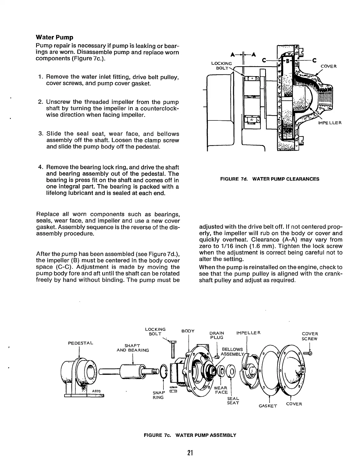
After the pump has been assembled (see Figure 7d.),
the impeller
(B)
must be centered
in
the body cover
space (C-C). Adjustment is made by moving the
pump body fore and aft until the shaft can be rotated
freely by hand without binding. The pump must be
..
.
i
..
FIGURE
7d.
WATER PUMP CLEARANCES
adjusted with the drive belt off. If not centered prop-
erly, the impeller will rub on the body or cover and
quickly overheat. Clearance (A-A) may vary from
zero to
1/16
inch
(1.6
mm). Tighten the lock screw
when the adjustment is correct being careful not to
alter the setting.
When the pump is reinstalled on theengine, check to
see that the pump pulley is aligned with the crank-
shaft pulley and adjust as required.
LOCKING
PEDESTAL
FIGURE
7c.
WATER PUMP ASSEMBLY
21
Redistribution or publication of this document,
by any means, is strictly prohibited.