Starting System
These models use a separate 12 volt starting motor
mounted on the
right
hand side of the engine to drive
the flywheel.
It
is a standard automotive starting
motor with a solenoid for engaging the pinion and an
over-running clutch. When the solenoid is energized,
its core pulls
in,
shifting the pinion into engagement
with the flywheel ring gear. At the same time, contacts
in the solenoid close to provide a circuit for the starter
motor. The starting motor remains engaged until the
starting switch is released.
If
engine is equipped with a start-disconnect switch, the starter
motor will automatically disengage flywheel gear when engine
speed reaches about
900
rpm.
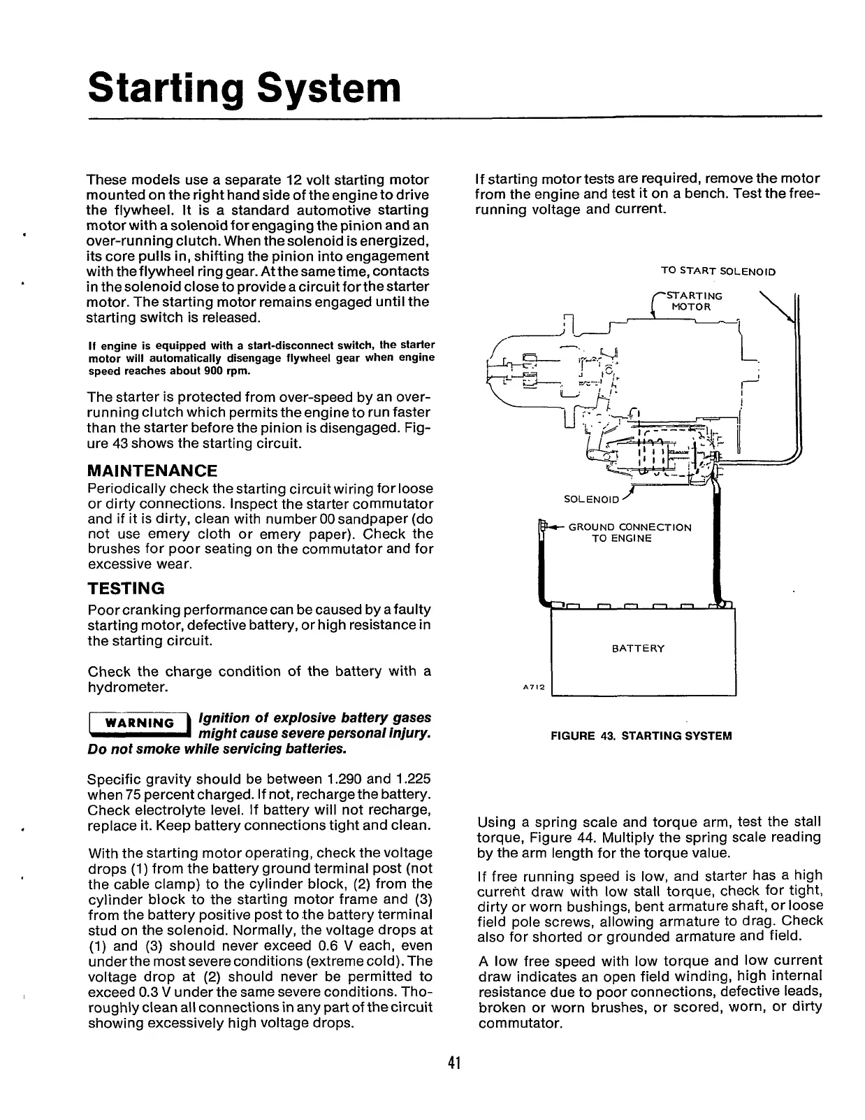
The starter is protected from over-speed by an over-
running clutch which permits the engine to run faster
than the starter before the pinion is disengaged. Fig-
ure
43
shows the starting circuit.
MAINTENANCE
Periodically check the starting circuit wiring for loose
or dirty connections. Inspect the starter commutator
and if it is dirty, clean with number
00
sandpaper (do
not use emery cloth or emery paper). Check the
brushes for poor seating on the commutator and for
excessive wear.
TESTING
Poor cranking performance can be caused by afaulty
starting motor, defective battery, or high resistance in
the starting circuit.
Check the charge condition of the battery with a
hydrometer.
Ignition
of
explosive baftery gases
might cause severe personal injury.
Do
not smoke while servicing batteries.
Specific gravity should be between 1.290 and 1.225
when
75
percent charged. If not, recharge the battery.
Check electrolyte level. If battery will not recharge,
replace it. Keep battery connections tight and clean.
With the starting motor operating, check the voltage
drops
(1)
from the battery ground terminal post (not
the cable clamp) to the cylinder block, (2) from the
cylinder block to the starting motor frame and
(3)
from the battery positive post to the battery terminal
stud on the solenoid. Normally, the voltage drops at
(1)
and
(3)
should never exceed
0.6
V
each, even
under the most severe conditions (extreme cold). The
voltage drop at (2) should never be permitted to
exceed
0.3
V
under the same severe conditions. Tho-
roughly clean all connections
in
any part
of
the circuit
showing excessively high voltage drops.
If
starting motortests are required, remove the motor
from the engine and test
it
on a bench. Test the free-
running voltage and current.
A712
I
FIGURE
43.
STARTING SYSTEM
Using a spring scale and torque arm, test the stall
torque, Figure
44.
Multiply the spring scale reading
by the arm length for the torque value.
If free running speed is low, and starter has a high
current draw with
low
stall torque, check for tight,
dirty or worn bushings, bent armature shaft, or loose
field pole screws, allowing armature to drag. Check
also for shorted or grounded armature and field.
A low free speed with low torque and low current
draw indicates an open field winding, high internal
resistance due to poor connections, defective leads,
broken or worn brushes, or scored, worn, or dirty
commutator.
41
Redistribution or publication of this document,
by any means, is strictly prohibited.