Fuel pump pressure may be checked by connecting a
pressure gauge and tee at the fuel outlet. A vacuum
the pump has enough capacity to lift fuel about
6
feet
(1.83 m). The fuel pump should produce 15
to
18
inches (381 to
457
mm) of vacuum at sea level.
7. Tighten cover screws alternately and securely,
then release rocker arm.
test.
gauge
connected
at
the
fuel inlet
will
show
whether
8.
Install
pump
on
the
engine
and repeat pressure
INJECTION NOZZLES
.1.
2.
3.
4.
5.
6.
7.
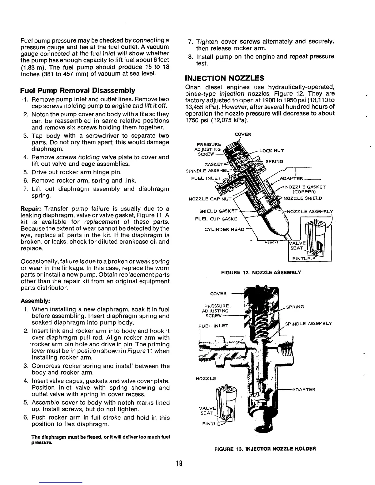
Onan diesel engines use hyd raul icall y-operated,
pintle-type injection nozzles, Figure
12.
They are
factory adjusted to open at 1900 to 1950
psi
(13,110 to
13.455 kPal. However. after several hundred hours
of
Fuel Pump
Removal
Disassembly
Remove Pump inlet and outlet lines. Remove two
cap screws holding pump to engine and
lift
it off.
Notch the pump cover and body with afileso they
can be reassembled in same relative positions
and remove six screws holding them together.
operation (he nozzle pressure will decrease to about
1750
psi (12,075 kPa).
Tao bodv with a screwdriver to seDarate two
COVER
paits. Ddnot pry them apart; this would damage
d ia p h rag m.
Remove screws holding valve plate to cover and
lift out valve and cage assemblies.
Drive out rocker arm hinge pin.
Remove rocker arm, spring and link.
Lift out diaphragm assembly and diaphragm
spring.
Repair:
Transfer pump failure is usually due to a
leaking diaphragm, valve or valve gasket, Figure 11. A
kit is available for replacement of these parts.
Because the extent of wear cannot be detected by the
eye, replace all parts in the kit. If the diaphragm is
broken, or leaks, check for diluted crankcase oil and
replace.
Occasionally, failure isdue to a broken orweak spring
or wear in the linkage. In this case, replace the worn
parts or install a new pump. Obtain replacement parts
other than the repair kit from an original equipment
parts distributor.
Assembly:
1.
When installing a new diaphragm, soak it in fuel
before assembling. Insert diaphragm spring and
soaked diaphragm into pump body.
2. Insert link and rocker arm into body and hook it
over diaphragm pull rod. Align rocker arm with
-rocker arm pin hole and drive in pin. The priming
lever must be
in
position shown
in
Figure
11
when
installing rocker arm.
3.
Compress rocker spring and install between the
body and rocker arm.
4.
Insert valve cages, gaskets and valve cover plate.
Position inlet valve with spring showing and
outlet valve with spring in cover recess.
5.
Assemble cover to body with notch marks lined
up. Install screws, but do not tighten.
6.
Push rocker arm in full stroke and hold
in
this
position to flex diaphragm.
PRESSURE
A
GASKET^
SPINDLE ASSEMBLY:
ADAPTER
-
NOZZLE GASKET
NOZZLE SHIELD
SHIELD CASK NOZZLE ASSEMBLY
FUEL CUP GASKE
CYLINDER HEAD
-
A00
FIGURE
12.
NOZZLE ASSEMBLY
COVER
4
SCREW
-+
FUEL INLET
A
NOZZ LE
PRESSURE
ADJUSTING
;ING
JDLE
rDAP'
ASS
TER
4BLY
The diaphragm must be flexed, or it
will
delivertoo much fuel
pressure.
FIGURE
13.
INJECTOR
NOZZLE
HOLDER
18
 Loading...
