PSU
Pump
Operation
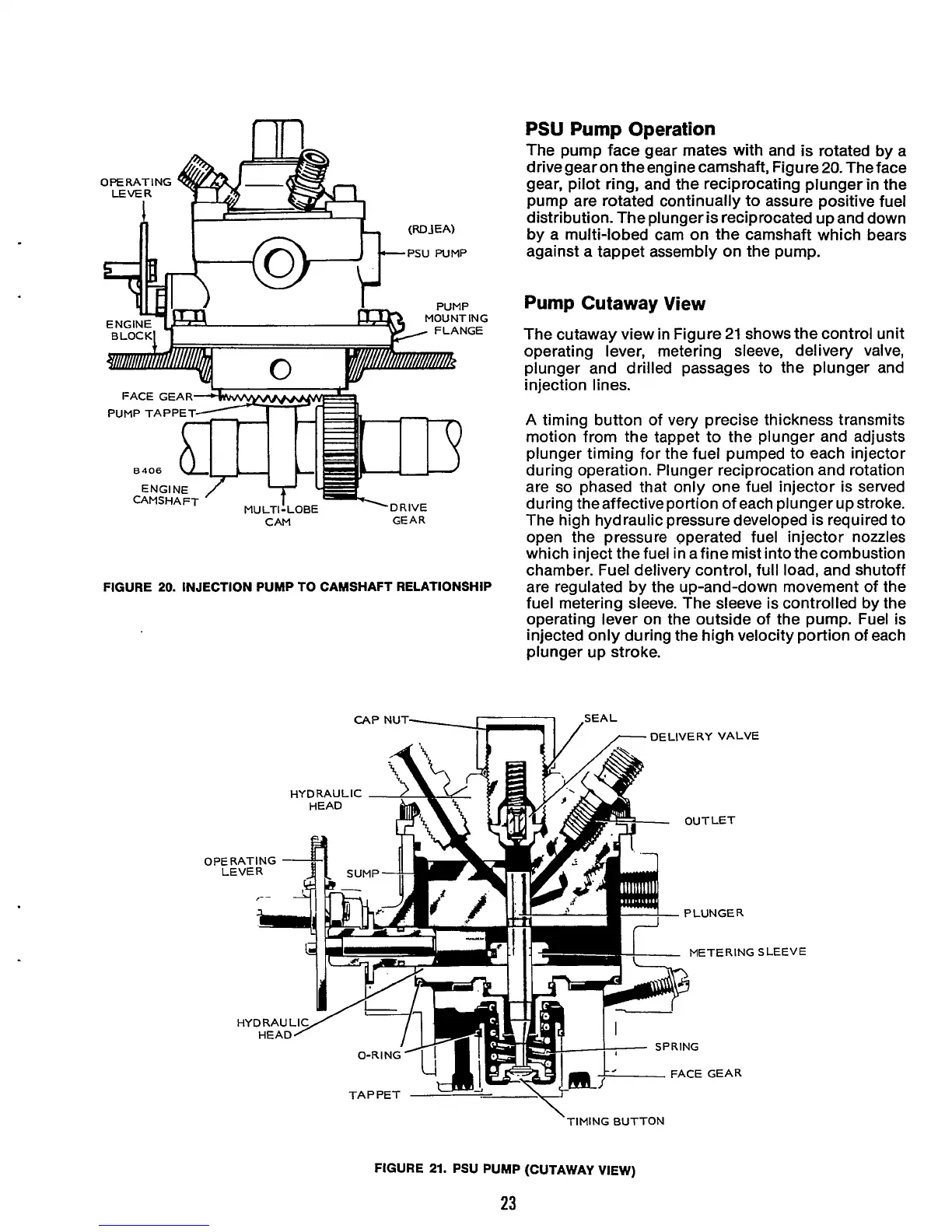
The pump face gear mates with and is rotated by a
drivegearon theengine camshaft, Figure20.Theface
gear, pilot ring, and the reciprocating plunger in the
pump are rotated continually to assure positive fuel
distribution. The plunger is reciprocated up and down
by a multi-lobed cam on the camshaft which bears
against a tappet assembly on the pump.
Pump
Cutaway
View
The cutaway view in Figure 21 shows the control unit
operating lever, metering sleeve, delivery valve,
plunger and drilled passages to the plunger and
injection lines.
A
timing button of very precise thickness transmits
motion from the tappet to the plunger and adjusts
plunger timing for the fuel pumped to each injector
during operation. Plunger reciprocation and rotation
are
so
phased that only one fuel injector is served
during the affective portion of each plunger up stroke.
CAM GEAR
The high hydraulic pressure developed is required to
open the pressure operated fuel injector nozzles
which inject the fuel in afine mist into thecombustion
chamber. Fuel delivery control, full load, and shutoff
are regulated by the up-and-down movement of the
fuel metering sleeve. The sleeve is controlled by the
operating lever on the outside of the pump. Fuel is
injected only during the high velocity portion
of
each
plunger up stroke.
MOUNTING
FLANGE
FIGURE
20.
INJECTION PUMP TO CAMSHAFT RELATIONSHIP
0
PE
L
LEEVE
\
TIMING BUTTON
FIGURE
21.
PSU PUMP (CUTAWAY VIEW)
23
 Loading...
