Seite / Page 11
150 50 59 / 01 - 2004
DeutschEnglish Abbildung / Figure
7 Federkraft
einstellen
HINWEIS - maximale
Zuladung an Federarmen:
Federarme sind zum Ausgleich des End-
geräte-Gewichtes mit unterschiedlichen
Federn ausgestattet. Bleibt der Federarm
mit Endgerät nach dem Einstellen der Fe-
derkraft nicht in der eingestellten Position
stehen, müssen die Federn durch einen
Service-Techniker gewechselt werden.
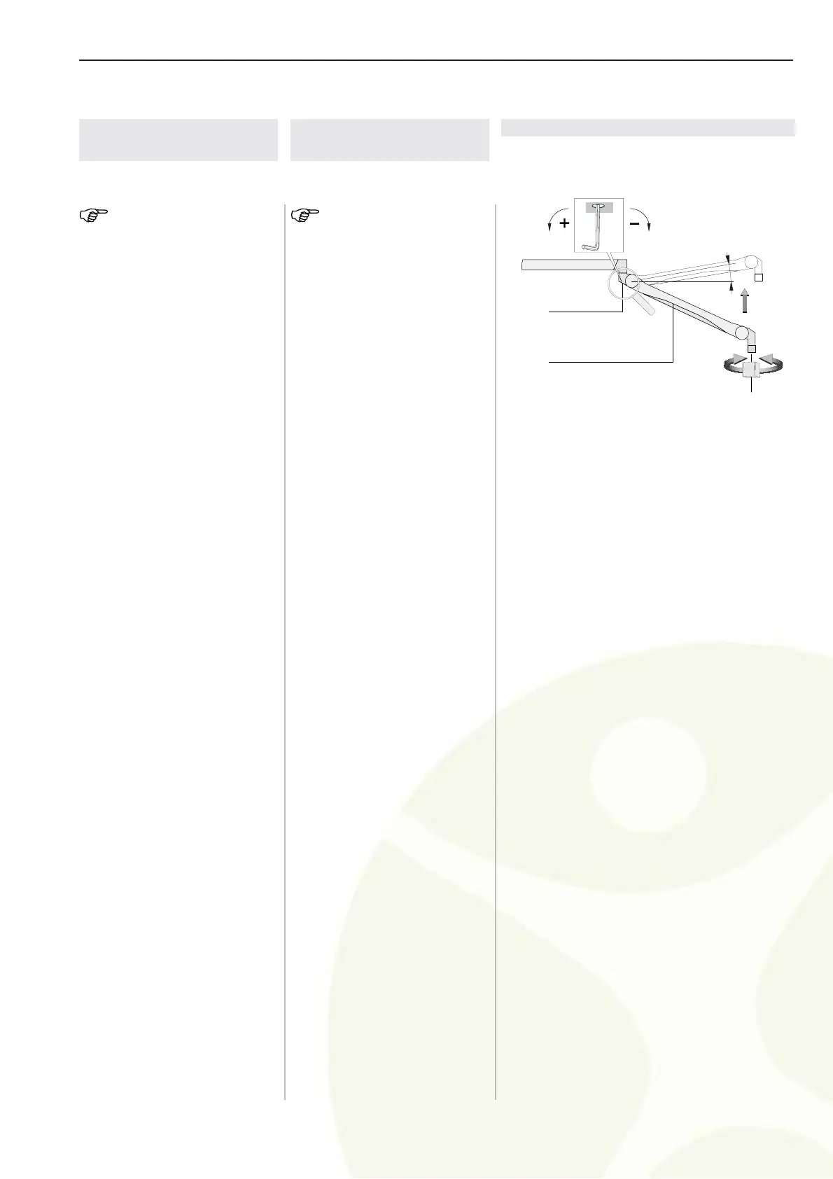
Federkraft so einstellen:
daß der Federarm mit Endgerät
in jeder gewünschten Position
stehen bleibt.
1. An der mit der Lupe gekenn-
zeichneten Positionen befin-
den sich eine Bohrung (1).
2. Federarm (2) mit Endgerät ca.
10° über die Horizontale stel-
len.
3. Sechskantschlüssel SW5 in
die Bohrung (1) stecken.
Sinkt der Federarm ab, ist die
Federkraft zu gering:
- die Einstellschraube muß
nach links in + Richtung (ge-
gen den Uhrzeigersinn) ge-
dreht werden.
Steigt der Federarm nach oben,
ist die Federkraft zu hoch:
- die Einstellschraube muß
nach rechts in - Richtung (im
Uhrzeigersinn) gedreht wer-
den.
Figure / Abbildung 6
1 Hole
Bohrung
2 Spring arm
Federarm
7 Adjusting the
spring force
NOTE - maximum additional
load at spring arms:
Spring arms are equipped with different
springs to compensate the end device
weight. If the spring arm with the end de-
vice cannot come to rest in any desired
position after the spring force has been
adjusted, the springs must be replaced by
a service technician.
To adjust the spring force:
make sure that the spring arm with
the end device can come to rest
in any desired position.
1. A hole (1) is located at the
positions marked with the rea-
ding glass.
2. Position the spring arm (2)
with the end device approxi-
mately 10° above horizontal.
3. Insert wrench (width 5) into the
hole (1).
If the spring arm drops, the
spring force is too low:
- rotate the adjustment screw to
the left (counterclockwise) in
the + direction.
If the spring arm rises, the spring
force is too high:
- rotate the adjustment screw to
the right (clockwise) in the -
direction.
 Loading...