1500 North Belcher Road, Clearwater, FL 33765 • Tel (727) 447-6140 • Fax (727) 442-5699 • sales@onicon.com
Turbine Flow Meter Manual 05/13 - 0721-1 / 13518 Page 9
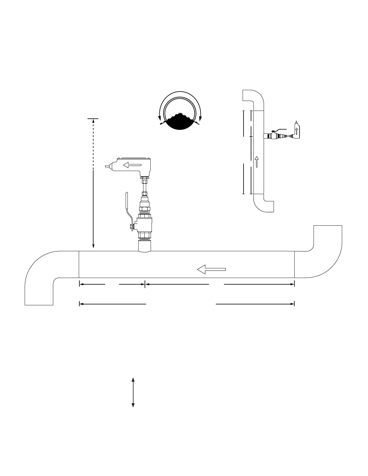
INSERTION AND INLINE FLOW METER SITE SELECTION
GENERAL GUIDELINES
(Shown with Insertion Meter)
• Install in vertical or horizontal pipe.
• For horizontal pipe position meter
anywhere in upper 240˚.
FLOW
20%
80%
Upstream
Downstream
Available Straight Run*
23" - 36"
Depending on
pipe size
CLEARANCE
REQUIRED
FOR INSTALLATION
FLOW
20%
80%
Upstream
Downstream
Available Straight Run*
Vertical pipe position
*See following pages for model specic straight run requirements.
EVALUATING UPSTREAM PIPING CONDITIONS
Straight Pipe
Single Bend
Pipe Reduction or Enlargement
Outowing Tees
Multiple Bends in Same Plane
Multiple Bends Out of Plane
Inowing Tees
Control Valves
Worse Better
CLEARANCE
REQUIRED
FOR INSTALLATION
23” - 36”
Depending on
pipe size
Allow at least
6” for inline meters
(Downward ow is also allowed)