Do you have a question about the Onkyo HT-R570 and is the answer not in the manual?
Visual breakdown of primary internal parts and their assembly.
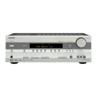
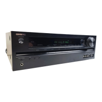
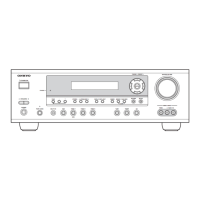
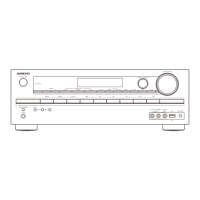
Visual breakdown of the front panel, buttons, and display.
Visual breakdown of the heatsink and power transistor mounting.
Diagram illustrating the audio signal path and processing flow.
Diagram detailing the video input, processing, and output pathways.
Diagram showing power distribution and voltage regulation.
Schematics showing internal cable connections between components.
Detailed circuit diagrams for speaker output terminals.
Circuit diagrams for front panel display and indicator functions.
Complete list of all parts with reference numbers and part numbers.
Specific parts list for the AV receiver's tuner section.
List of transistors, diodes, and ICs used within the unit.
| HDMI Outputs | 1 |
|---|---|
| FM Tuner | Yes |
| THD | 0.08 % |
| Input Sensitivity | 200 mV |
| Audio D/A Converter | 192kHz/24-bit |
| Tuner Presets | 40 |
| Audio Formats Supported | Dolby Digital, DTS |
| Amplifier Output Details | 130 W per channel (6 ohms, 1 kHz, 1% THD, 1 channel driven) |
| Response Bandwidth | 10 Hz - 100 kHz |
| Input Impedance | 47 kΩ |
| Built-in Decoders | Dolby Digital, DTS |
| Sound Effects | Theater-Dimensional |
| Tuning Range | FM: 87.5 - 107.9 MHz |
| Connectivity | HDMI |
| Frequency Response | 10 Hz - 100 kHz |