Do you have a question about the Onkyo TX-NR828(B) and is the answer not in the manual?
Critical components identified by mark are critical for risk of fire and electric shock.
Procedure for replacing fuses, ensuring correct type and rating for fire hazard protection.
Perform safety checks, including leakage current measurement, before unit release.
Procedure to initialize the unit by pressing specific buttons, resulting in a 'CLEAR' display.
Steps to display and check versions of Main Microprocessor (MMPU) and other firmware.
Caution regarding high voltages on the power supply board even after power disconnection.
Display mode to check audio information, operations of DSP and DIR for diagnosing audio issues.
Details on input signals, sampling frequencies, and sound states displayed in audio debug mode.
Information on input format, sampling frequency, and number of channels for listening mode transition.
Details on PC resolution, input/output formats, and emphasis information for HDMI and PC signals.
Check HDMI-related operations by displaying HDMI debug mode information.
Display of output resolution for video processors, DVI, VGA, and 4K upscaling.
Details on HDMI input mode, color, deep color, and 3D format.
Check PC resolution display for DVI and HDMI inputs/outputs, including EDID.
Display service information to analyze unit status, especially when in Protect mode or powered off.
Checks for voltage detection, current detection, RDS, headphone, USB, network, and sensor operations.
Confirms HDMI audio operations (I2S, SPDIF, DSD) and video output signals for various inputs.
Confirms video signal detection, 12V trigger, cooling fan, Wi-Fi connection, and miscellaneous operations.
Details on test modes for model, destination, FL display, and general operation checks.
Provides detailed test modes for various inputs, including analog, digital, and USB sources.
Details on auto measurement modes for DSP output channels, voltage, and protection circuits.
Covers video and HDMI test modes, including input selector, signal types, and preset memory writing.
Details on cooling fan operation conditions, circuit, and how to check thermal and VOLH values.
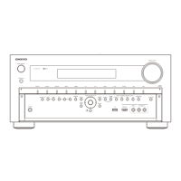
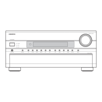
Shows an overall exploded view of the unit, including WiFi & Bluetooth module details.
Provides an exploded view of the front panel components and their assembly.
Contains FCC and IC compliance statements, including RF exposure guidelines and cautionary notices.
Diagram showing the power supply circuit, including AC power input, primary, and secondary sections.
Diagram illustrating the RS232, 12V trigger, and IR input sections of the unit.
Diagram for the front HDMI and USB connectors, including the MHL interface.
Diagram detailing the HDMI input and output connections, MHL control, and SPARTA section.
Illustrates the HDMI input switching and SD video decoder sections of the unit.
Diagram of the video processor section, showing connections to HDMI, MPU, and VSP.
Diagram of the digital audio interface (DIR) and DAC (Digital-to-Analog Converter) section.
Diagram showing the Wi-Fi/Bluetooth module connector and BPF PC board connections.
| Brand | Onkyo |
|---|---|
| Model | TX-NR828(B) |
| Category | Stereo Receiver |
| Language | English |